
Prefabricated column connecting structure

A technology for connecting structures and prefabricated columns, which is applied in the direction of columns, pillars, pier columns, etc., can solve the problems of low installation efficiency, high cost, and the inability of the steel bars of prefabricated columns to be inserted into the sleeve accurately, so as to improve installation efficiency and installation cost Low height, avoid misalignment and misalignment effect

Pending Publication Date: 2021-10-22
程金彪
View PDF0 Cites 0 Cited by
  • Summary
  • Abstract
  • Description
  • Claims
  • Application Information

AI Technical Summary

Problems solved by technology

[0004] In order to solve the above-mentioned problems, the present invention provides a connection structure of prefabricated columns to solve the problem that the existing prefabricated columns are connected through sleeve grouting, which has high cost and low installation efficiency, and the steel bars of the prefabricated columns cannot be accurately inserted into the sleeves. The problem

Method used


Image

  • Prefabricated column connecting structure
  • Prefabricated column connecting structure
  • Prefabricated column connecting structure

Examples


Embodiment Construction

[0029] The implementation of the present invention will be illustrated by specific specific examples below, and those skilled in the art can easily understand other advantages and effects of the present invention from the contents disclosed in this specification.

[0030] It should be noted that the structures, proportions, sizes, etc. shown in the drawings attached to this specification are only used to match the content disclosed in the specification, for those who are familiar with this technology to understand and read, and are not used to limit the implementation of the present invention. Limiting conditions, so there is no technical substantive meaning, any modification of structure, change of proportional relationship or adjustment of size, without affecting the effect and purpose of the present invention, should still fall within the scope of the present invention. The disclosed technical content must be within the scope covered. At the same time, terms such as "upper"...


PUM


Abstract

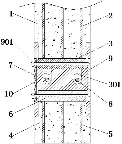
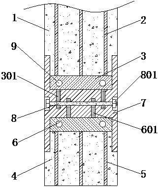
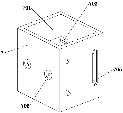
The invention provides a prefabricated column connecting structure, which comprises a prefabricated column, a foundation and a connecting piece, wherein a plurality of prefabricated column steel bars are evenly embedded in the prefabricated column; the upper surface of a first connecting plate is welded to the bottom parts of the prefabricated column steel bars; a plurality of first inserting feet are welded to the left end and the right end of the lower surface of the first connecting plate; a plurality of pre-embedded steel bars are evenly embedded in the foundation; a second connecting plate is embedded in the upper surface of the foundation; a plurality of second inserting feet are welded to the left end and the right end of the upper surface of the second connecting plate; an upper connecting groove is arranged on the upper surface of the connecting piece; a plurality of first inserting grooves are arranged on the bottom surface of the upper connecting groove; a lower connecting groove is arranged on the bottom surface of the connecting piece; a plurality of second inserting grooves are arranged on the top surface of the lower connecting groove; bolts are in threaded connection in the first threaded through holes; and a U-shaped bolt is inserted into each first through hole. Due to the fact that the connecting piece is matched with the prefabricated column and the foundation, the prefabricated column can be installed conveniently and rapidly, and the manufacturing cost is not high.

Description

technical field [0001] The invention relates to the technical field of building structures, and more specifically relates to a connection structure of prefabricated columns. Background technique [0002] Columns are elongated members used to support beams and trusses in buildings. In the engineering structure, the vertical rods that mainly bear the pressure and sometimes bear the bending moment are used to support beams, trusses, floors, etc. In traditional construction projects, the supporting columns are cast on site. But for prefabricated buildings, a large number of building parts are produced and processed by the workshop, and then assembled directly on the construction site, which greatly improves the construction speed and efficiency of the building. [0003] At present, the installation of prefabricated columns adopts the method of sleeve grouting to connect the column to the foundation and column to column. However, the connection method of sleeve grouting has high...

Claims


Application Information

Patent Timeline
Patent Type & Authority Applications(China)
IPC IPC(8): E04B1/21E04C3/34E04B1/41
CPCE04B1/21E04C3/34E04B1/215E04B1/41
Inventor 不公告发明人
Owner 程金彪
Learn More