Mounting and fixing assembly of LED down lamp

A technology of LED downlights and fixing components, which is applied in the parts of lighting devices, semiconductor devices of light-emitting elements, lighting devices, etc., can solve the problems of poor adaptability, inconvenient installation and disassembly of downlights, etc., so as to improve adaptability and ensure installation Fixed effect, convenience-enhancing effect

Active Publication Date: 2021-10-22
汉思科技集团股份有限公司
View PDF8 Cites 0 Cited by
  • Summary
  • Abstract
  • Description
  • Claims
  • Application Information

AI Technical Summary

Problems solved by technology

[0005] The object of the present invention is to provide a mounting and fixing assembly for an LED downlight, which connects the wedge-shaped plate through the rotation of the outer cylinder, drives the wedge-shaped plate to rotate through the rotation of the lamp tube, and utilizes the wedge-shaped The lower surface of the board gradually presses down on the ceiling to realize the fixation of the downlight, which solves the problems of inconvenient installation and disassembly of the existing downlight and poor adaptability

Method used


Image

  • Mounting and fixing assembly of LED down lamp
  • Mounting and fixing assembly of LED down lamp
  • Mounting and fixing assembly of LED down lamp

Examples


Embodiment 1

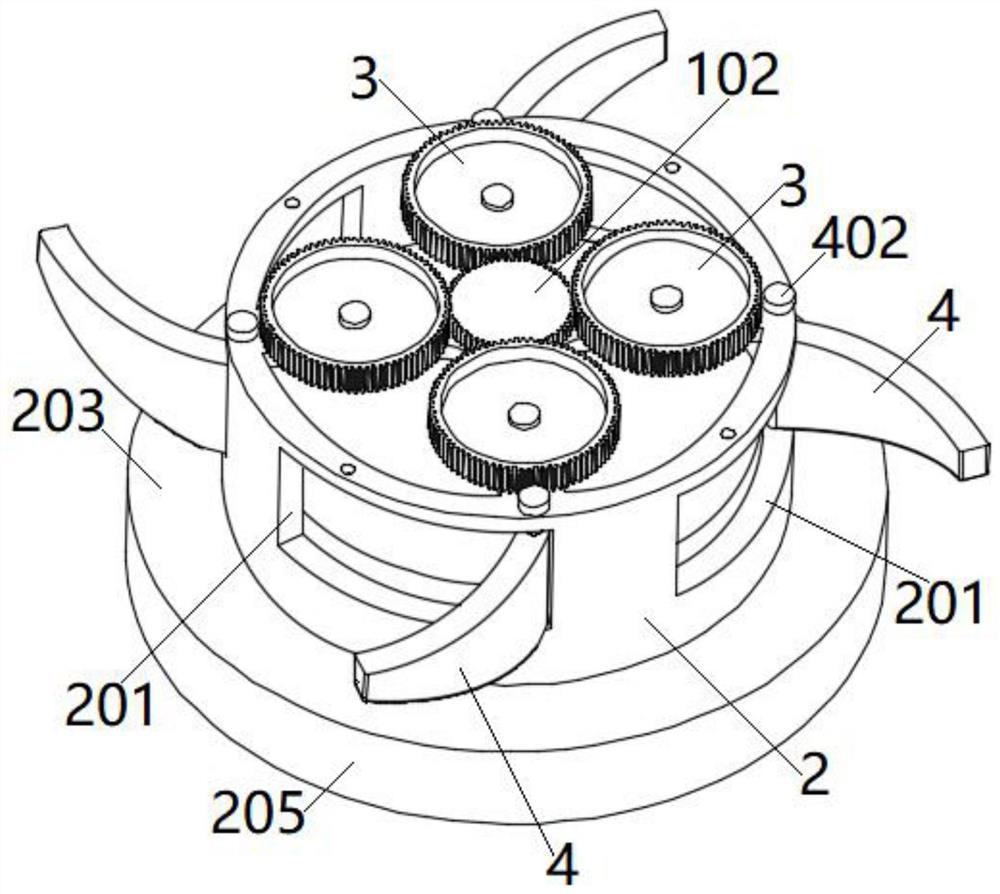
[0034] see figure 1 and 2 As shown, the present invention is an installation and fixing assembly of an LED downlight, including a lamp canister 1, an outer tube 2 is sleeved on the outer wall of the lamp canister 1, and a receiving slot 201 is evenly distributed on the circumference of the side wall of the outer tube 2. The receiving slot The number of 20 is three to six, preferably four.

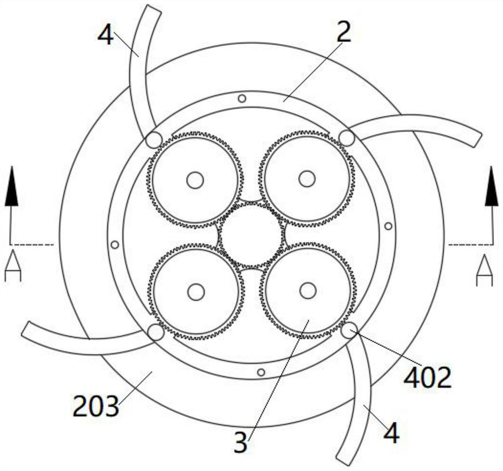
[0035] like Figure 3-6 As shown, a mounting plate 202 is fixedly connected to the upper end surface of the outer cylinder 2, and a flange 203 is provided at the lower end of the outer cylinder 2; The mounting plate 202 is provided with connecting holes 204 , and four transition wheels 3 are rotatably connected;

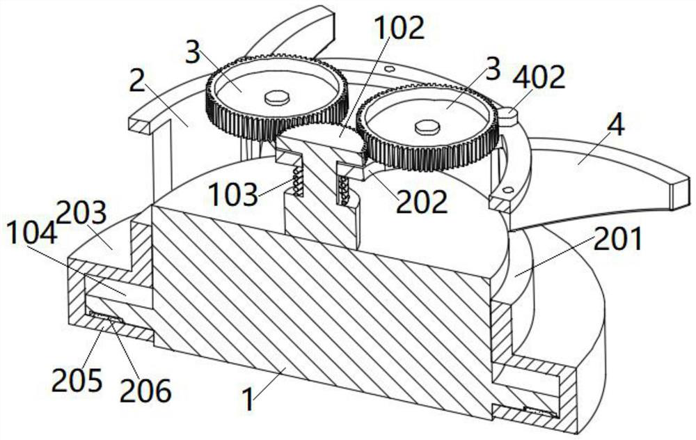
[0036] like Figure 7 As shown, the wedge-shaped plate 4 is rotatably connected in the receiving slot 201 , the inner bottom surface and the inner top surface of the receiving slot 201 are both provided with mounting holes, and the mounting hole on the inner top surface is a t...

Embodiment 2

[0043] like Figure 4-6 As shown, on the basis of the first embodiment, the connecting shaft 101 has a stepped shaft structure; the connecting shaft 101 is sleeved with a compression spring 103 ; offset.

[0044] At the same time, an annular folded plate 205 is fixedly connected to the peripheral side surface of the flange 203 , and the flange 203 and the annular folded plate 205 can be fixed by clip connection or screw connection or adhesion. The cross-sectional shape of the annular folded plate 205 is L-shape; the upper surface of the bottom wall of the annular folded plate 205 is provided with limit blocks 206 evenly distributed around the circumference.

[0045]The outer wall of the lamp tube 1 is provided with a retaining ring 104 ; the retaining ring 104 is located between the flange 203 and the annular folded plate 205 , and limiting notches 105 corresponding to the limiting blocks 206 are evenly distributed on the lower surface of the retaining ring 104 . Through the...


PUM


Abstract

The invention discloses a mounting and fixing assembly of an LED down lamp, and relates to the technical field of lamps. The mounting and fixing assembly comprises a lamp cylinder. The outer wall of the lamp cylinder is sleeved with an outer cylinder. Storage notches are uniformly formed in the circumference of the side wall of the outer cylinder; the upper end of the outer cylinder is connected with a mounting plate and the lower end is provided with a flange; the mounting plate is provided with a connecting hole and is rotationally connected with a plurality of transition wheels; a wedge-shaped plate is rotationally connected into the storage notches; the wedge-shaped plate is connected with a rotating shaft; the upper end of the rotating shaft penetrates through the upper surface of the outer cylinder and is connected with a driven wheel meshed with the transition wheels; the upper end of the lamp cylinder is connected with a connecting shaft; and the connecting shaft is connected with a driving wheel meshed with the transition wheels. Through rotation of the wedge-shaped plate, an inclined lower surface is used for gradually pressing a ceiling downwards, and the wedge-shaped plate is matched with the flange to clamp the outer cylinder on the ceiling, so that the convenience of mounting and dismounting of the down lamp is effectively improved, the down lamp can adapt to ceilings with different thicknesses, the adaptability to the ceilings with different thicknesses is effectively improved, and the mounting and fixing effects are ensured.

Description

technical field [0001] The invention belongs to the technical field of lamps, and in particular relates to a mounting and fixing assembly for an LED downlight. Background technique [0002] Downlight is a type of lighting fixture that is embedded in the ceiling. In the existing downlight, a torsion spring is usually used to fix the downlight during use. However, when the downlight needs to be disassembled and maintained in the later stage, the downlight is very inconvenient to disassemble, and the ceiling is easily damaged. [0003] At the same time, due to the different thickness of the ceiling during decoration, when it is too thick or too thin, the existing downlight fixing method cannot adapt to the thickness of the ceiling, resulting in a poor installation effect of the downlight. [0004] Therefore, there is an urgent need to design between the existing downlight installation and fixing methods, so as to improve the convenience of installation and disassembly of the d...

Claims


Application Information

Patent Timeline
Patent Type & Authority Applications(China)
IPC IPC(8): F21V21/02F21Y115/10
CPCF21V21/02F21Y2115/10
Inventor 何庆亮
Owner 汉思科技集团股份有限公司
Why Eureka
Try Eureka