
Speed-measuring light-reflecting device

A speed-measuring reflective and reflective technology, which is applied in the use of devices for measuring the time required to move a certain distance, radio wave measurement systems, electromagnetic wave re-radiation, etc., can solve problems such as low measurement accuracy and inaccurate measurement results

Pending Publication Date: 2021-10-22
ZHENJIANG MINGRUN INFORMATION TECH
View PDF0 Cites 0 Cited by
  • Summary
  • Abstract
  • Description
  • Claims
  • Application Information

AI Technical Summary

Problems solved by technology

[0003] This method is simple and easy to use, but the measurement accuracy is not high. Generally, only one reflective sheet is pasted on one axis. When pasting more than one, the measurement result will be inaccurate due to the uniformity of pasting, position deviation, etc.

Method used


Image

  • Speed-measuring light-reflecting device
  • Speed-measuring light-reflecting device

Examples


Embodiment Construction

[0017] The following will clearly and completely describe the technical solutions in the embodiments of the present invention with reference to the accompanying drawings in the embodiments of the present invention. Obviously, the described embodiments are only some, not all, embodiments of the present invention. Based on the embodiments of the present invention, all other embodiments obtained by persons of ordinary skill in the art without making creative efforts belong to the protection scope of the present invention.

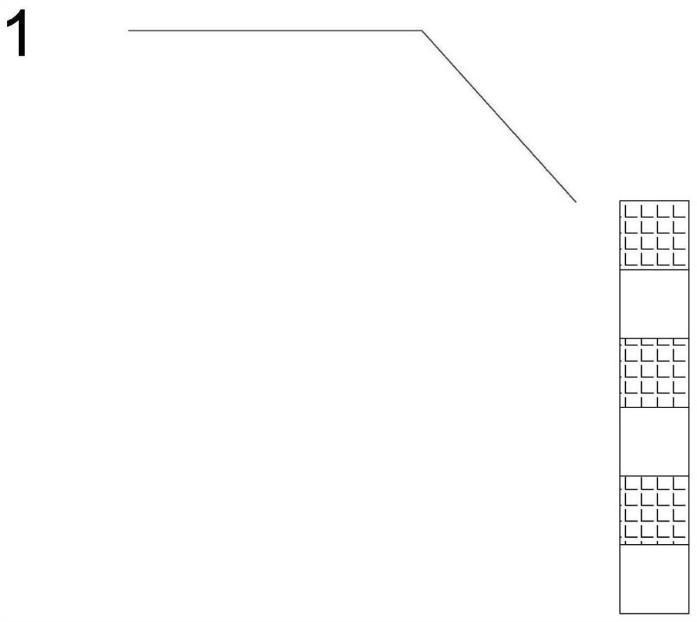
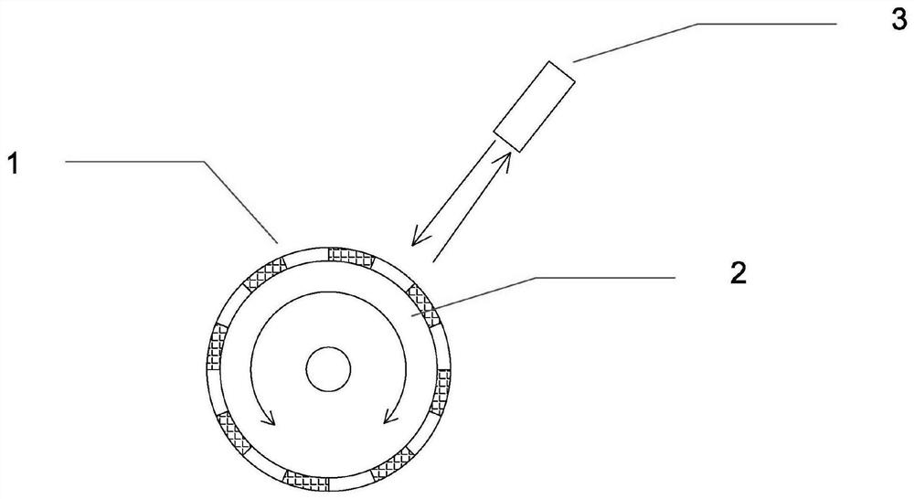
[0018] Such as Figures 1 to 2 As shown, this embodiment provides a speed-measuring reflective device, which includes a rotating part, and eight reflective areas and eight non-reflective areas are arranged on the outside of the rotating part along the circumferential direction.

[0019] In this specific embodiment, the rotating part includes a rotating shaft 2 driven by a power mechanism. The power mechanism may be a motor, and the rotating shaft 2 is connecte...


PUM


Abstract

The invention, which relates to the technical field of the rotating shaft measuring mechanism, discloses a speed-measuring light-reflecting device comprising a rotating part, and the outer part of the rotating part is provided with at least one light-reflecting area and at least one non-light-reflecting area along the circumferential direction. The reflective areas and the non-reflective areas are arranged on the same reflective strip product, so that the reflective areas and the non-reflective areas are ensured to have consistent sizes and intervals, and the problem of inaccurate measurement results caused by pasting uniformity, position deviation and the like when a plurality of reflective sheets are pasted is solved.

Description

technical field [0001] The invention relates to the technical field of a rotating shaft measuring mechanism, in particular to a speed measuring reflective device. Background technique [0002] The existing method of measuring the rotational speed of the rotating shaft has a method of providing pulses to measure the rotational speed based on the difference in the intensity of the reflected light. The existing method of providing the difference in the intensity of the reflected light is to paste a single reflective sheet on one axis. When the measuring device is on the rotating axis The light intensity measured at the position of the reflector and the position without the reflector are different to distinguish the pulses, and the number and interval of the pulses are statistically analyzed to measure the rotational speed of the rotating shaft. [0003] This method is simple and easy to use, but the measurement accuracy is not high. Generally, only one reflective sheet is paste...

Claims


Application Information

Patent Timeline
Patent Type & Authority Applications(China)
IPC IPC(8): G01P3/68
CPCG01P3/68
Inventor 华文博朱小明
Owner ZHENJIANG MINGRUN INFORMATION TECH
Learn More