
Zoom lens

A technology of zoom lens and lens, which is applied in the field of zoom lens to achieve the effects of reducing light height, ensuring image quality, and good focus

Pending Publication Date: 2021-10-22
舜宇光学(中山)有限公司
View PDF0 Cites 2 Cited by
  • Summary
  • Abstract
  • Description
  • Claims
  • Application Information

AI Technical Summary

Problems solved by technology

However, zoom lenses in the prior art generally cannot meet the above requirements

Method used


Image

  • Zoom lens
  • Zoom lens
  • Zoom lens

Examples


Embodiment Construction

[0056] In order to more clearly describe the embodiments of the present invention or the technical solutions in the prior art, the following will briefly introduce the drawings that are used in the embodiments. Apparently, the drawings in the following description are only some embodiments of the present invention, and those skilled in the art can also obtain other drawings according to these drawings without creative efforts.

[0057] When describing the embodiments of the present invention, the terms "vertical", "transverse", "upper", "lower", "front", "rear", "left", "right", "vertical", " The orientation or positional relationship expressed by "horizontal", "top", "bottom", "inner" and "outer" is based on the orientation or positional relationship shown in the relevant drawings, which are only for the convenience of describing the present invention and simplifying the description, and It is not to indicate or imply that the device or element referred to must have a particu...


PUM


Abstract

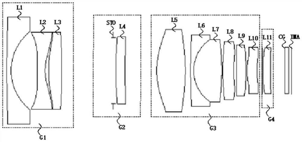
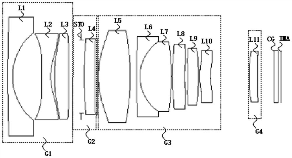
The invention relates to a zoom lens which comprises a compensation group (G1) with negative focal power, a first fixed group (G2) with positive focal power and a zoom group (G3) with positive focal power which are sequentially arranged from an object side to an image side along an optical axis, and further comprises a second fixed group (G4) located on the image side of the zoom group (G3). In the zooming process, the first fixed group (G2) and the second fixed group (G4) are fixed relative to image plane positions, and the compensation group (G1) and the zoom group (G3) can move along an optical axis. The zoom lens provided by the invention has the characteristics of ultra-large aperture, large target surface and low cost.

Description

technical field [0001] The invention relates to the technical field of optical imaging, in particular to a zoom lens. Background technique [0002] The zoom lens has the characteristic of variable focal length, which can meet the needs of various monitoring scenarios, so it has attracted widespread attention in the security monitoring market. The rapid popularization and development of security monitoring also have higher requirements for the image acquisition function of the lens. A zoom lens with a powerful image acquisition function needs to ensure a large aperture zoom within the full focal length range while meeting the high resolution and large target area. In this way, even in the case of insufficient external fill light, it is still possible to shoot high-definition picture quality. In order to expand the use scenarios of this type of lens, the zoom lens also needs to have the performance of not defocusing at a low temperature of -40°C to a high temperature of 80°C...

Claims


Application Information

Patent Timeline
Patent Type & Authority Applications(China)
IPC IPC(8): G02B15/14G02B15/177G02B13/00G02B13/18
CPCG02B15/144515G02B15/177G02B13/0015G02B13/0045G02B13/009
Inventor 蓝岚沈悦
Owner 舜宇光学(中山)有限公司
Learn More