
Cutting unit with wave-shaped cutting edge

A wavy, cutting-edge technology, applied in metal processing and other directions, can solve problems such as difficult trimming of transitional parts

Pending Publication Date: 2021-10-26
WAHL
View PDF15 Cites 0 Cited by
  • Summary
  • Abstract
  • Description
  • Claims
  • Application Information

AI Technical Summary

Problems solved by technology

Therefore, trimming transitions is more difficult with this hair clipper, as small missteps immediately stand out when clipping transitions

Method used


Image

  • Cutting unit with wave-shaped cutting edge
  • Cutting unit with wave-shaped cutting edge
  • Cutting unit with wave-shaped cutting edge

Examples


Embodiment Construction

[0063] In the following, the direction "front" means the direction of the tooth element (for example, in Figure 4b the top side of the), direction "rear" means the opposite direction (in the Figure 4b the lower side of the ).

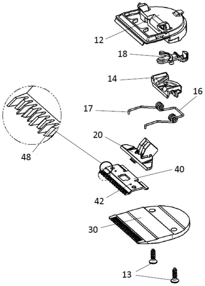
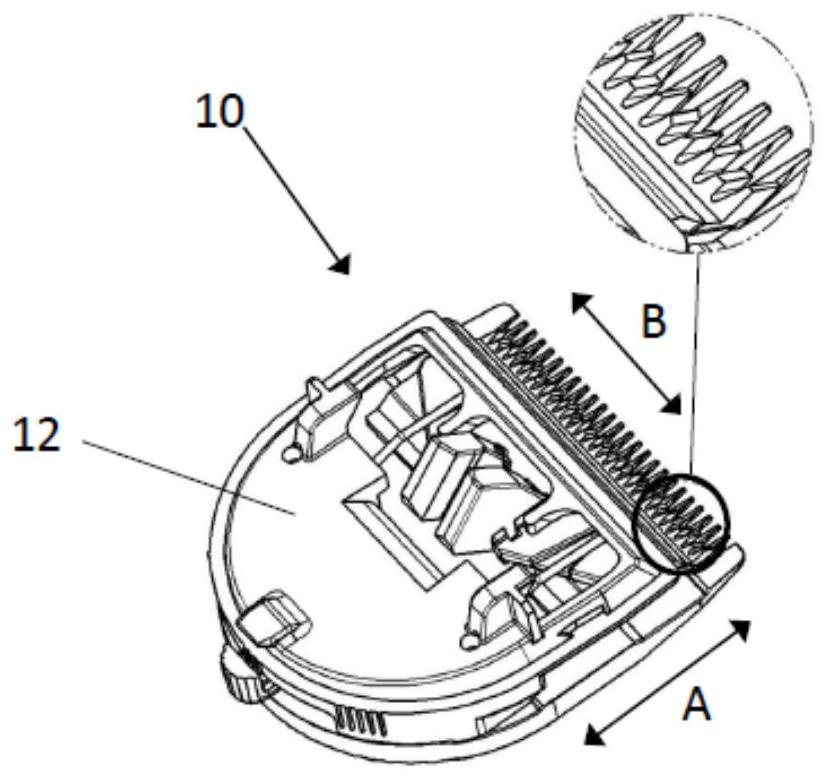
[0064] figure 1 An exploded view of the components of the blade arrangement 10 according to the invention is shown. exist figure 2 , the blade unit is shown installed. figure 1 and figure 2 The blade unit in the upper side is placed on the handle and attached to the driver, which creates an oscillating motion. The motor for this drive is placed in the handle, which is common in hair clippers.

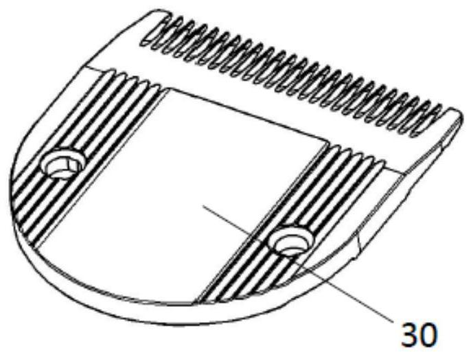
[0065]The blade arrangement 10 comprises a comb 30 , blades 40 , 50 , 60 , 70 , a pretensioning element 16 as spring element 16 and a connecting device. The connecting means are used to connect the comb 30 and the upper blades 40, 50, 60, 70 and comprise a plurality of parts which may vary in function and number. In the embodiment shown, the connectin...


PUM


Abstract

A blade arrangement for a hair clipper comprises a comb with an anterior edge, which contains tooth elements; a blade with an anterior cutting edge, which contains tooth elements, with the anterior cutting edge being downwardly sloped towards the lower cutting edge, and the blade being configured to be movable relative to the comb; a connecting device, which connects the comb and the blade relatively movable to each other; and a pretension element, which preloads the comb and the blade against each other. The device is characterized in that the cutting edge of the blade has a wave shape, the anterior cutting edge of the blade contains at least three tooth elements and / or the edges of each tooth element have a curved shape according to the wave shape.

Description

technical field [0001] The present invention relates to a trimmer for a hair clipper with corrugated cutting edges. Background technique [0002] In the prior art, various hair clippers with different blade sets are known. For example, US Pat. No. 7,841,901 B2 discloses a blade set for a hair clipper comprising at least one fixed blade with a plurality of fixed blade teeth and at least one movable blade with a plurality of fixed blade teeth, The blades are configured to reciprocate laterally relative to at least one stationary blade to trim hair. The movable blade includes a set of long teeth configured to trim hair across the width of the movable blade and a set of short teeth configured to cut hair across the width of the movable blade when the hair clipper is advanced above a specified speed. Trim the hair in the upward direction. [0003] US Pat. No. 5,933,953 discloses a hair clipper for trimming strands of hair having a blade set having a fixed blade with a pluralit...

Claims


Application Information

Patent Timeline
Patent Type & Authority Applications(China)
IPC IPC(8): B26B19/04B26B19/38
CPCB26B19/04B26B19/3846B26B19/205B26B19/12B26B19/20
Inventor G·埃明格尔
Owner WAHL
Learn More