Communication equipment mounting frame

A communication equipment and mounting frame technology, which is applied to mechanical equipment, electrical equipment structural parts, engine frames, etc., can solve the problems of bolt detachment, bolt loosening, mounting frame and communication equipment falling, etc., so as to strengthen the fixing strength, Strengthen the fixing effect and improve the efficiency of disassembly and maintenance

Pending Publication Date: 2021-10-26
周倩婷
View PDF0 Cites 0 Cited by
  • Summary
  • Abstract
  • Description
  • Claims
  • Application Information

AI Technical Summary

Problems solved by technology

[0003] In summary, the inventors found that the existing mounting frame mainly has the following defects: when the mounting frame installs a single communication device on an outdoor column, the bottom end of the mounting frame is in a flat state so that it can only pass through its own bottom. The center position of the end and the contact surface of the top of the column are fixed with corresponding bolts, so that the two sides will directly form a hollow state, so that when the top encounters strong wind, the hollow state on both sides is easy to be continuously pushed by the strong wind, so that the center bolt will be indirectly. Looseness occurs, so as the number of times is superimposed, it is easy to form a situation where the bolts are separated from the top of the column, resulting in the situation that the mounting bracket and the communication equipment will fall from a high place directly.

Method used


Image

  • Communication equipment mounting frame
  • Communication equipment mounting frame
  • Communication equipment mounting frame

Examples


Embodiment 1

[0028] Figure 1 to Figure 6 Shown:

[0029] The invention provides a communication equipment installation frame,

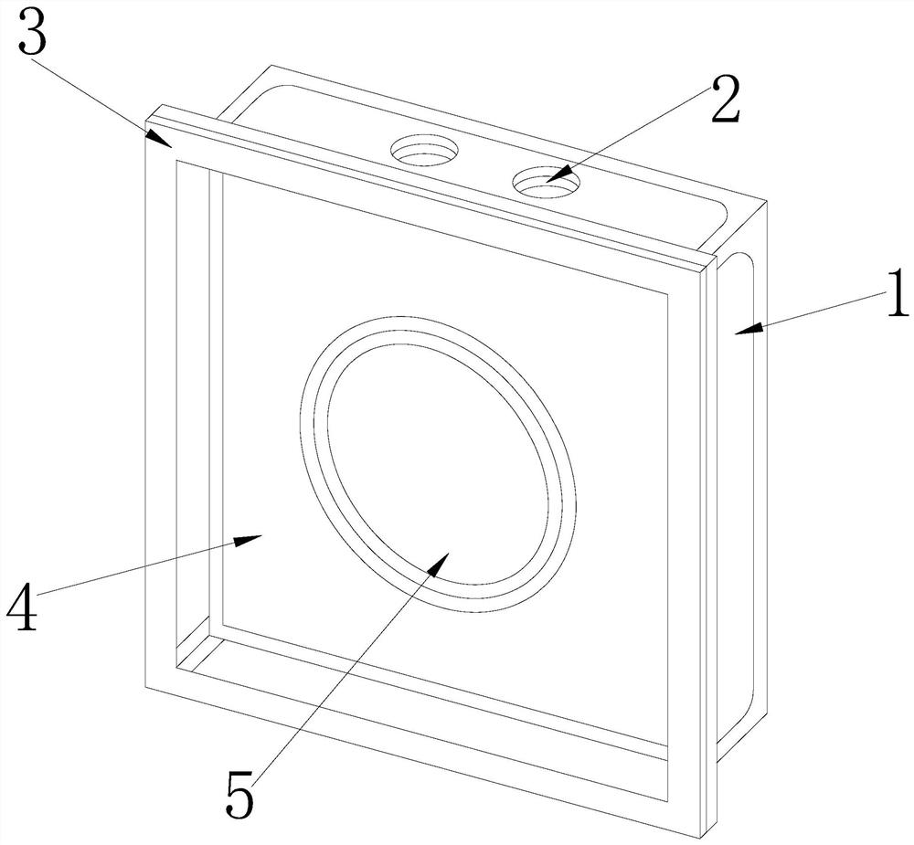
[0030] Its structure includes: installation box 1, vent hole 2, installation frame 3, groove body 4, connecting ring 5, the installation box 1 and the ventilation hole 2 are integrated, and the installation frame 3 is engaged with the front end of the installation box 1 To connect, the tank body 4 is embedded in the installation frame 3 , and the connecting ring 5 is fixedly connected to the tank body 4 .

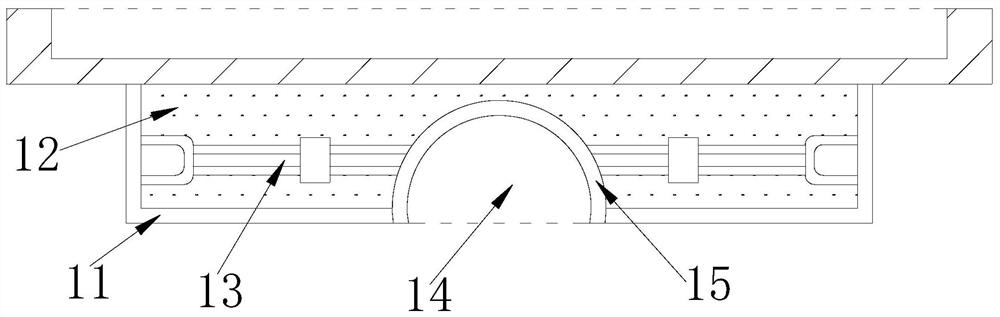
[0031] The installation box 1 is provided with a shell 11, a movable layer 12, a telescopic rod 13, a hole 14, and an insertion block 15. The shell 11 and the movable layer 12 are integrated, and the telescopic rod 13 is installed in the movable layer 12, so that The hole 14 is embedded in the lower end of the movable layer 12, and the insertion block 15 is integrated with the hole 14 and is movably connected with the telescopic rod 13. One is provided to f...

Embodiment 2

[0039] Figure 7 to Figure 9 Shown:

[0040] The invention provides a communication equipment installation frame,

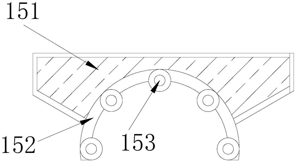
[0041] Its structure includes that the ball 153 is provided with a limit ring c1, a lifting frame c2, and an introduction groove c3, the lower part of the limit ring c1 communicates with the lifting frame c2, the introduction groove c3 is embedded in the lifting frame c2, and the Corresponding fitting pieces are provided inside the limiting ring c1 and the number is the same as that of the components. The limiting ring c1 can effectively improve the fixed-point rotation effect of each component and increase the positioning through the corresponding fitting pieces.

[0042] Wherein, the lifting frame c2 is provided with a fixed rod c21, a runner c22, a fitting block c23, and a connecting block c24, the fixed rod c21 and the runner c22 are in clearance fit, and the fitting block c23 is installed on the runner c22 The side part of the connecting block c24 is fixed...


PUM


Abstract

The invention provides a communication equipment mounting frame. The communication equipment mounting frame structurally comprises a mounting box, an air hole, a mounting frame, a groove body and a connecting ring, wherein the mounting box and the air hole are integrated, the mounting frame is connected with the front end of the mounting box in a clamped mode, the groove body is embedded in the mounting frame, and the connecting ring is fixedly connected to the interior of the groove body. According to the communication equipment mounting frame, the mounting box is improved, and then the diameter of the mounting box is adjusted through a telescopic rod to be fixed in a stand column when the mounting box is inserted into the top end of the stand column through an inserting block and a hole; the smoothness of insertion can be improved through balls of a contact plate, and strong wind above the mounting box can be effectively guided through a positioning block at the top end to the hole so as to relieve the impact of the strong wind; and the communication equipment can be correspondingly cooled during relieving, meanwhile, the fixing strength of the communication equipment can be enhanced through a movable frame and a fixing plate of a through hole, and the corresponding convenient effect on subsequent disassembling, assembling and maintenance of the communication equipment can be achieved.

Description

technical field [0001] The invention relates to the technical field of communication, and more specifically relates to a communication equipment installation frame. Background technique [0002] With the continuous development of communication technology, it is necessary to maintain the corresponding communication signals through many communication devices, so that the communication devices can be effectively positioned and fixed through the mounting bracket, which can effectively prevent direct contact with the ground. Affected by moisture or dust impurities in the air; [0003] In summary, the inventors found that the existing mounting frame mainly has the following defects: when the mounting frame installs a single communication device on an outdoor column, the bottom end of the mounting frame is in a flat state so that it can only pass through its own bottom. The center position of the end and the contact surface of the top of the column are fixed with corresponding bol...

Claims


Application Information

Patent Timeline
Patent Type & Authority Applications(China)
IPC IPC(8): F16M13/02F16M7/00H05K7/20
CPCF16M13/022F16M7/00H05K7/20127
Inventor 周倩婷
Owner 周倩婷
Why Eureka
Try Eureka