
Magnetic type movable linear wall lamp

A magnetic and linear technology, applied in lighting devices, fixed lighting devices, electric light sources, etc., can solve the problems of inconvenient disassembly and assembly of linear wall lamps, inconvenient linear wall lamps, and easily damaged walls, so as to facilitate maintenance and ensure normal operation , the effect of reducing the likelihood

Pending Publication Date: 2021-10-26
JIANGSU LVSUNNY VISION TECH CO LTD
View PDF0 Cites 0 Cited by
  • Summary
  • Abstract
  • Description
  • Claims
  • Application Information

AI Technical Summary

Problems solved by technology

[0003] After the linear wall lamp is installed on the wall, it is generally difficult to disassemble and assemble. If the user needs to rearrange the room, change the position of the linear wall lamp or repair and replace the linear wall lamp, it is inconvenient to disassemble the linear wall lamp and easily damage the wall. The user adjusts the position of the linear wall light or performs maintenance on the linear wall light

Method used


Image

  • Magnetic type movable linear wall lamp
  • Magnetic type movable linear wall lamp
  • Magnetic type movable linear wall lamp

Examples


Embodiment 1

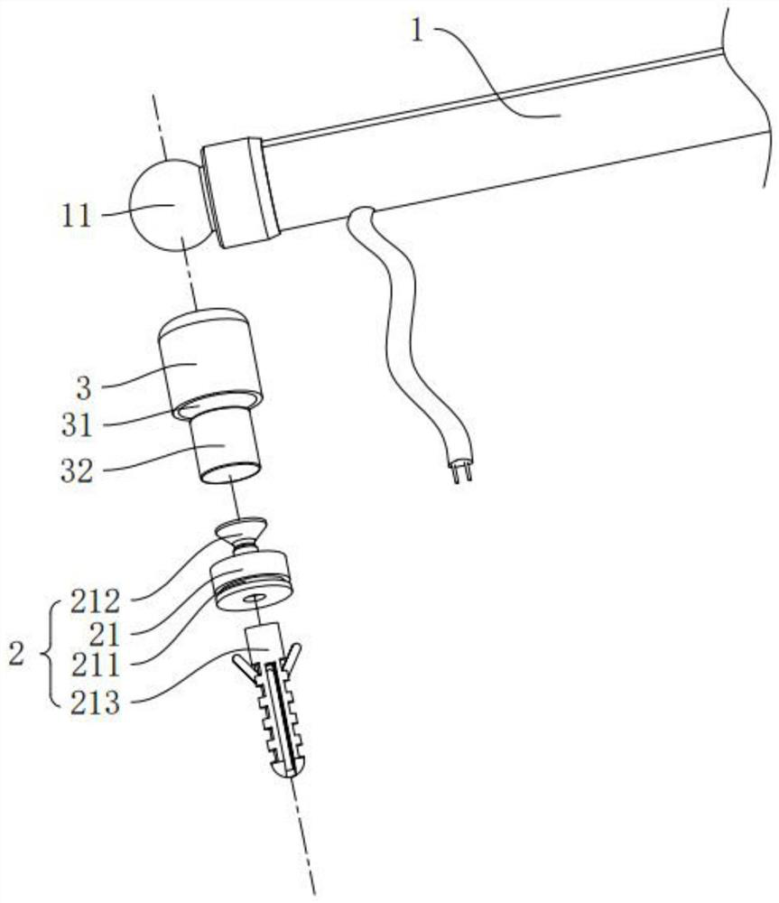
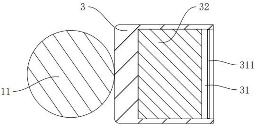
[0029] refer to figure 1 and figure 2 , the present application provides a magnetic movable linear wall lamp, which includes a lamp 1 and a set of installation parts. The end faces of the two ends of the lamp 1 are respectively fixedly connected with a first magnetic member 11, and the first magnetic member 11 The shape is spherical, and the center of the sphere of the first magnetic member 11 coincides with the axis of the lamp 1 . There are two installation parts in the same group, and both installation parts are installed on the wall. There is a second magnetic attraction 32 inside the installation part, and the two second magnetic attraction 32 correspond to the two first magnetic attraction 11 respectively, and the first magnetic attraction 11 and the corresponding second magnetic attraction 32 are attracted to each other. , the lamp 1 can be adsorbed on the two installation parts.

[0030] It should be noted that during actual installation, multiple sets of mounting ...

Embodiment 2

[0038] refer to Figure 4The difference between this embodiment and the first embodiment lies in that the outer surface of the first magnetic member 11 is a deflection surface 111 . A second groove 33 is provided on the end face of the positioning member 3 without the receiving groove 31, and the inner wall of the second groove 33 is a curved surface. When the first magnetic member 11 and the second magnetic member 32 are attracted to each other, The first magnetic element 11 can be embedded in the second groove 33, and the deflection surface 111 is attached to the inner wall of the second groove 33, that is, after the first magnetic element 11 is embedded in the second groove 33, the lamp 1 (Fig. (not shown in the figure) can rotate around its own axis, driving the first magnetic member 11 to rotate relative to the second groove 33 .

[0039] In addition, the notch edge of the second groove 33 is also processed with a circular arc chamfer 331 , so as to prevent the first mag...


PUM


Abstract

The invention relates to a magnetic type movable linear wall lamp which comprises a lamp and at least one group of mounting parts. At least two first magnetic parts are arranged on the lamp, the number of the mounting parts in the same group is the same as that of the first magnetic parts, and each mounting part comprises a connecting piece mounted on a wall surface, and second magnetic attraction pieces arranged on the connecting pieces. The second magnetic attraction pieces and the first magnetic attraction pieces in the same group are in one-to-one correspondence, and the second magnetic attraction pieces and the corresponding first magnetic attraction pieces attract each other so that the lamp can be installed on the wall surface. The linear wall lamp has the effect that a user can conveniently adjust the position of the linear wall lamp or maintain the linear wall lamp.

Description

technical field [0001] The invention relates to the field of wall lamps, in particular to a magnetic suction movable linear wall lamp. Background technique [0002] Linear wall lamps have the advantages of simplicity and beauty, so they are loved by more and more young people in home decoration. Linear wall lamps are generally arranged along the wall, directly bolted to the wall or installed on the wall in the form of bonding. [0003] After the linear wall lamp is installed on the wall, it is generally difficult to disassemble and assemble. If the user needs to rearrange the room, change the position of the linear wall lamp or repair and replace the linear wall lamp, it is inconvenient to disassemble the linear wall lamp and easily damage the wall. The user adjusts the position of the linear wall light or performs maintenance on the linear wall light. Contents of the invention [0004] Aiming at the deficiencies of the prior art above, the object of the present invention...

Claims


Application Information

Patent Timeline
Patent Type & Authority Applications(China)
IPC IPC(8): F21S8/00F21V21/096F21V21/14
CPCF21S8/033F21V21/096F21V21/14
Inventor 徐恒刘占国
Owner JIANGSU LVSUNNY VISION TECH CO LTD
Learn More