Supercharge Your Innovation With Domain-Expert AI Agents!

Bar-shaped displacement code, bar-shaped displacement code ruler and displacement detection device

A technology of displacement detection and displacement, which is applied in the direction of measuring devices, mechanical measuring devices, and mechanical devices, etc. It can solve the problems of displacement detection errors, incompletely parallel motion directions, and the inability to mark compensation positions with bar displacement codes, so as to improve measurement Accuracy, the effect of avoiding thread clearance error

Active Publication Date: 2021-10-26
李里
View PDF26 Cites 2 Cited by
  • Summary
  • Abstract
  • Description
  • Claims
  • Application Information

AI Technical Summary

Problems solved by technology

[0002] Application No. 2020104453646 discloses a bar displacement code, a bar displacement yardstick and a displacement detection device. The scanning line of the linear array image sensor is perpendicular to the position bar, and the bar displacement yardstick and the linear array image sensor move in a relative straight line, ideally Under normal circumstances, within the entire displacement detection range, there is only one intersection point between the scanning line and the center line of each position bar, that is, the imaging center position of the position bar remains unchanged, but in reality, the scanning line of the line array image sensor and the bar displacement The movement direction of the code ruler is not completely parallel, which makes the scanning line swing slightly on the position bar, and the position bar has burrs and distortions. If such burrs and distortions are not compensated, it will directly cause displacement detection errors. For high-precision displacement The detection device is unacceptable; the compensation of burr and distortion requires a corresponding compensation position mark, and this compensation position mark is unique within the displacement detection range, but the bar displacement code in the application number 2020104453646 scheme cannot mark the compensation position

Method used


Image

  • Bar-shaped displacement code, bar-shaped displacement code ruler and displacement detection device
  • Bar-shaped displacement code, bar-shaped displacement code ruler and displacement detection device
  • Bar-shaped displacement code, bar-shaped displacement code ruler and displacement detection device

Examples


Embodiment Construction

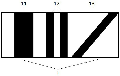
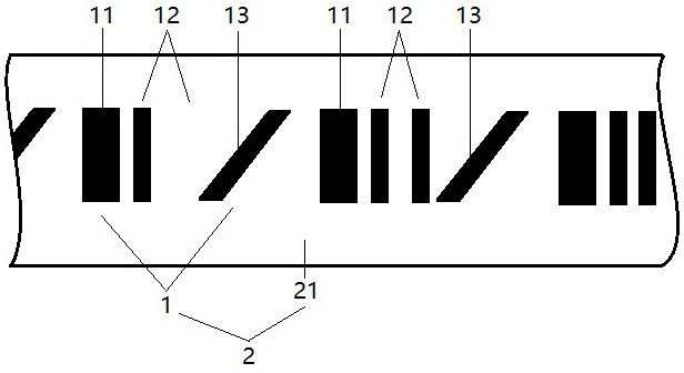
[0021] A bar displacement code 1, such as figure 2 As shown, it includes a position bar 11 and a number bar 12, the position bar 11 is used for displacement subdivision detection, and is perpendicular to the direction of displacement measurement; the number bar 12 is set by binary code, and its code value represents the bar displacement code The serial number of 1 is used for displacement section detection, and is parallel to the position bar 11 .

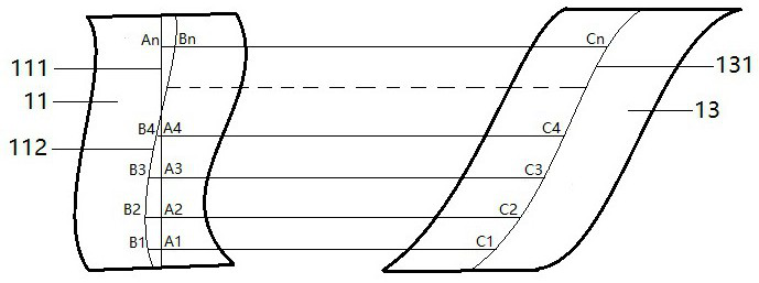
[0022] Due to the unavoidable presence of burrs and twists in the position strip 11, such as figure 1 As shown in , the burr and distortion must be compensated, and the compensation amount and the corresponding compensation position mark of each burr and distortion must be stored. The compensation position mark corresponds to the position of the burr and distortion one by one, so in A compensation bar 13 is added to the bar displacement code 1, and the compensation bar 13 forms an angle θ with the position bar 11, 10°<θ<90°.

[...


PUM


Abstract

The invention discloses a bar-shaped displacement code, a bar-shaped displacement code ruler and a displacement detection device, the bar-shaped displacement code comprises a position bar, a number bar and a compensation bar, the position bar is parallel to the number bar, an angle [theta] is formed between the position bar and the compensation bar, and [theta] is more than 10 degrees and less than 90 degrees; the bar-shaped displacement code is manufactured on the ruler surface of the bar-shaped displacement code ruler, and the bar-shaped displacement code is perpendicular to the displacement detection direction; and the bar-shaped displacement code ruler and the linear array image sensor form a displacement detection device.

Description

technical field [0001] The application belongs to the field of length measurement, and relates to a bar displacement code, a bar displacement yardstick and a displacement detection device. Background technique [0002] Application No. 2020104453646 discloses a bar displacement code, a bar displacement yardstick and a displacement detection device. The scanning line of the linear array image sensor is perpendicular to the position bar, and the bar displacement yardstick and the linear array image sensor move in a relative straight line, ideally Under normal circumstances, within the entire displacement detection range, there is only one intersection point between the scanning line and the center line of each position bar, that is, the imaging center position of the position bar remains unchanged, but in reality, the scanning line of the line array image sensor and the bar displacement The movement direction of the code ruler is not completely parallel, which makes the scannin...

Claims


Application Information

Patent Timeline
IPC IPC(8): G01B5/02
CPCG01B5/02
Inventor 李乐航李里李宏明
Owner 李里
Features
  • R&D
  • Intellectual Property
  • Life Sciences
  • Materials
  • Tech Scout
  • Unparalleled Data Quality
  • Higher Quality Content
  • 60% Fewer Hallucinations
Learn More