

A Method for Obtaining Mode Shape Angle of Hemispherical Resonant Gyroscope When Errors Exist in Electrode Angle
A hemispherical resonant gyro and angle error technology, which is applied in the inertial field, can solve the problems that the hemispherical resonant gyroscope cannot achieve accurate angle measurement and low accuracy, and achieve the effects of improving navigation accuracy, improving measurement accuracy, and improving angle measurement accuracy
- Summary
- Abstract
- Description
- Claims
- Application Information
AI Technical Summary
Problems solved by technology
Method used
Image

Examples
specific Embodiment approach 1
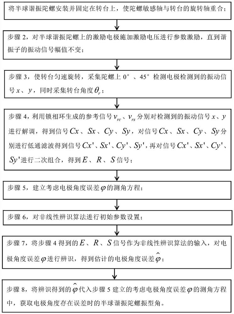
[0021] Embodiment 1: Combining figure 1 This embodiment is described. The specific process of a method for obtaining the mode angle of a hemispherical resonant gyroscope when there is an error in the electrode angle in this embodiment is as follows:
[0022] The invention proposes a method for obtaining the mode angle of the hemispherical resonant gyroscope when there is an error in the electrode angle. to identify. The method obtains an accurate angle measurement formula by identifying the electrode angle error, thereby calculating the precise mode angle of the resonator, and realizing the high-precision angle measurement of the gyroscope. The present invention can also realize the identification of the electrode angle error by extending nonlinear identification algorithms such as Kalman filtering.
[0023] Step 1, install and fix the hemispherical resonant gyroscope on the turntable, so that the sensitive axis of the gyroscope coincides with the rotation axis of the turnt...
specific Embodiment approach 2
[0031] Embodiment 2: The difference between this embodiment and Embodiment 1 is that in the step 2, the excitation electrodes are arranged on the hemispherical resonant gyroscope at intervals. like Figure 4 shown.
[0032] Other steps and parameters are the same as in the first embodiment.
specific Embodiment approach 3
[0033] Embodiment 3: The difference between this embodiment and Embodiment 1 or 2 is that the reference signal v generated by the phase-locked loop is used in the step 4. rc , v rs Demodulate the detected vibration signals x and y respectively to obtain the signals Cx, Sx, Cy, and Sy, and perform low-pass filtering on the signals Cx, Sx, Cy, and Sy to obtain the signals Cx', Sx', Cy', Sy ', and then combine the signals Cx', Sx', Cy', Sy' twice to obtain the E, R, S signals; the specific process is:
[0034] The reference signal v generated by the phase-locked loop rc , v rs Demodulate the detected vibration signals x and y respectively to obtain the signals Cx, Sx, Cy, and Sy. The expressions are:
[0035]
[0036] The signals Cx, Sx, Cy, and Sy are subjected to low-pass filtering to filter out the double frequency in the signals Cx, Sx, Cy, and Sy, respectively, to obtain the signals Cx', Sx', Cy', Sy';
[0037] The signals Cx', Sx', Cy', and Sy' are combined twice to ...
PUM
 Abstract
Description
Claims
Application Information