Optical disk apparatus

An optical disc device and optical disc technology, applied to the configuration/installation of the head, optical recording/reproduction, instruments, etc., can solve the problems of large contact area, cost increase, thick plate spring, etc.

Inactive Publication Date: 2004-01-21
ALPS ALPINE CO LTD
View PDF0 Cites 0 Cited by
  • Summary
  • Abstract
  • Description
  • Claims
  • Application Information

AI Technical Summary

Problems solved by technology

[0015] However, in such an optical disc device 100 in the prior art, when the optical disc device 100 is subjected to shocks or the like during transmission or the like, the guide shafts 104, 105 may inhibit the elasticity of the plate springs 108, 109, 110. Therefore, in order to prevent it from falling off from the frame housing 101 toward the outside, it is necessary to use its elastic force ratio than the optical disc device 100 in normal use (such as recording or reproducing the optical disc, etc.). Plate springs 108-110 with a much larger elastic force for problem-free support of the guide shafts 104, 105
Therefore, when bolts 111-113 are used to install and fix the plate springs 108-110 on the frame housing 101, in order to prevent the frame housing 101 from being deformed under the relatively large elastic force, it is also necessary to make The thickness of the sheet metal used to make the rack shell is relatively thick, which will increase the cost
[0016] Moreover, because the elastic force applied to the guide shafts 104, 105 is relatively large, the thickness of the plate spring itself is relatively thick, and the contact area with the guide shafts 104, 105 will be relatively large, so that its area must be increased. This will further increase the cost
[0017] Moreover, since the installation work of the plate springs 108-110 must be carried out under the condition of suppressing a relatively large elastic force, it is necessary to use a relatively large force to keep the plate springs 108-110 at the installation position on the surface of the frame housing 101. This will make the installation torque of the bolts 111~113 relatively large, which in turn will reduce the workability
[0018] Moreover, although in the prior art example as described above, the elastic member employs a plate spring, when such a coil spring is employed, the same problem also arises.
Moreover, although this prior art example employs the frame case 101 made of sheet metal, the same problem also arises when a frame case made of a resinous material or the like is used.

Method used


Image

  • Optical disk apparatus
  • Optical disk apparatus
  • Optical disk apparatus

Examples


Embodiment Construction

[0031] Referring to accompanying drawings 1 to attached Figure 5 , an optical disc device as an embodiment of the present invention will be described.

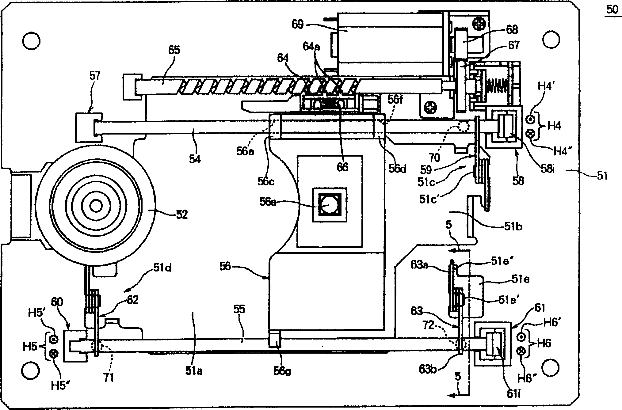
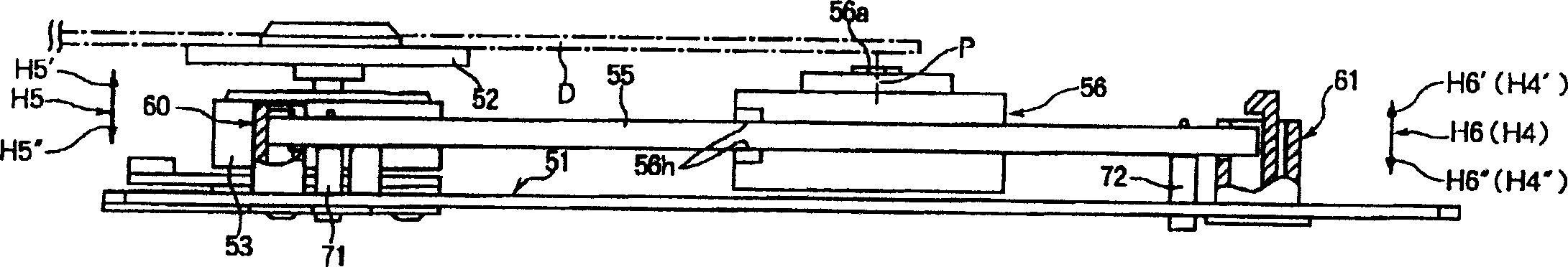
[0032] Figure 1A , Figure 1B It is a plan view and a partially cutaway side view showing an optical disc device 50 as an embodiment of the present invention. The optical disc device 50 mainly includes a rectangular frame housing 51 made of sheet metal, and a spindle motor 53 disposed on the frame housing 51 and integrally formed coaxially with the turntable 52 is arranged parallel to each other. The guide shafts 54, 55 have an optical sensor 56 having a partially arcuate recessed portion of the objective lens 56a arranged between the guide shafts 54, 55, and a substantially rectangular shape, and along the guide shafts 54, The longitudinal direction of 55 implements the transmission mechanism which will be described later for the optical sensor 56 .

[0033] Next, the configuration of the optical disc device 50 will be ...


PUM


Abstract

An optical disc unit is disclosed, comprising a turntable on which an optical disc is placed, an optical pickup, guide shafts for guiding the optical pickup radially of the optical disc, first and second support members, as well as third and fourth support members, for supporting the guides shafts respectively, the turntable, the optical pickup, the guide shafts, and the first to fourth support members being disposed on a chassis, the second and fourth support members being respectively provided with pawl pieces spaced a predetermined gap from end portions of the guide shafts. Near the second and fourth support members are disposed adjust screws for adjusting the height of end portions of the guide shafts, as well as torsion coil springs for urging the guide shafts elastically. When the above end portions of the guide shafts are displaced away from upper end faces of the adjust screws, the displacement is restricted by the pawl pieces of the second and fourth support members.

Description

technical field [0001] The present invention relates to an optical disc device which can be loaded into an optical disc and record or reproduce information. Background technique [0002] An optical disc device is a device that can be loaded into an optical disc, irradiates a laser beam to the information recording surface of the optical disc, and then records information on the information recording surface, or reproduces the recorded information. [0003] Figure 6 It is a perspective view showing an optical disc device 100 in the prior art. The optical disc device 100 mainly includes a substantially rectangular rack case 101 made of metal plate with a partial cutout formed on the outer edge. The spindle motor 103 integrally formed in a shape, the guide shafts 104, 105 arranged parallel to each other, the optical sensor 106 having an objective lens 106a arranged between the guide shafts 104, 105, and having a substantially rectangular shape, and the The longitudinal direc...

Claims


Application Information

Patent Timeline
Patent Type & Authority Patents(China)
IPC IPC(8): G11B21/02G11B7/08G11B7/085
CPCG11B7/08582G11B21/02
Inventor 加贺谷浩之浅野贵宏
Owner ALPS ALPINE CO LTD
Why Eureka
Try Eureka