Anti-overload MEMS movable structure with strain self-counteracting function
What is Al technical title?
Al technical title is built by PatSnap Al team. It summarizes the technical point description of the patent document.
An anti-overload, strain beam technology, applied in microstructure devices composed of deformable elements, microstructure technology, piezoelectric effect/electrostrictive or magnetostrictive motors, etc., can solve elastic beam deformation structural damage , low stiffness of elastic beam, large displacement in the direction of mass movement, etc., to achieve the effect of reducing internal stress, high stiffness, and limiting large displacement of the structure
Active Publication Date: 2022-03-25
BEIJING INST OF AEROSPACE CONTROL DEVICES
View PDF8 Cites 0 Cited by
Summary
Abstract
Description
Claims
Application Information
AI Technical Summary
This helps you quickly interpret patents by identifying the three key elements:
Problems solved by technology
Method used
Benefits of technology
Problems solved by technology
However, the stiffness of the elastic beam is low. When the gyroscope is subjected to a large external impact, the mass block will have a large displacement in the direction of motion, which may collide with other structures or cause structural damage due to excessive deformation of the elastic beam.
Method used
Image
Click on the blue label to locate the original text in one second.
Reading with bidirectional positioning of images and text.
Examples
Embodiment Construction
[0028] Exemplary embodiments of the present disclosure will be described in more detail below with reference to the accompanying drawings. Although exemplary embodiments of the present disclosure are shown in the drawings, it should be understood that the present disclosure may be embodied in various forms and should not be limited by the embodiments set forth herein. Rather, these embodiments are provided for more thorough understanding of the present disclosure and to fully convey the scope of the present disclosure to those skilled in the art. It should be noted that, in the case of no conflict, the embodiments of the present invention and the features in the embodiments can be combined with each other. The present invention will be described in detail below with reference to the accompanying drawings and examples.
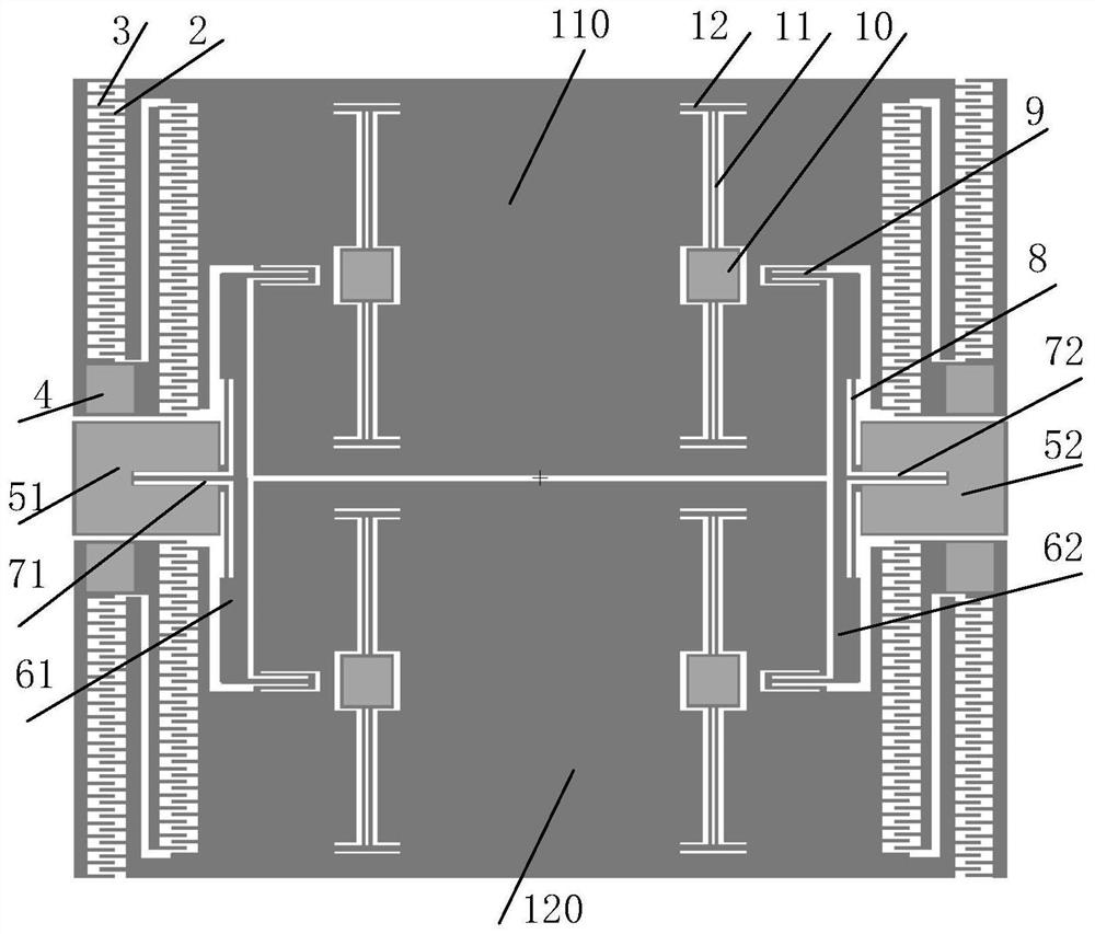
[0029] figure 1 It is a schematic diagram of an anti-overload MEMS movable structure with strain self-offsetting provided by an embodiment of the present inv...
PUM
Abstract
The invention discloses an anti-overload MEMS (Micro Electro Mechanical System) movable structure with a strain self-counteracting function. Comprising a first movable mass block, a second movable mass block, a first structural unit, a second structural unit, a third structural unit, a fourth structural unit, a first anti-overload fixing anchor area, a second anti-overload fixing anchor area, a first anti-overload strain beam, a second anti-overload strain beam, a first anti-overload supporting beam and a second anti-overload supporting beam. Wherein the first structural unit, the second structural unit, the third structural unit and the fourth structural unit are the same in structure, and each of the first structural unit, the second structural unit, the third structural unit and the fourth structural unit comprises a mass block comb tooth, a driving comb tooth, a driving comb tooth anchor area, a rotary vibration beam, a rotary adjusting beam, a bending vibration beam fixed anchor area, a bending vibration beam and a stress release beam. According to the invention, structural fracture caused by overlarge structural displacement when the movable MEMS structure is subjected to large impact in the movement direction is avoided, the method can be applied to MEMS gyroscope structural design, the anti-overload characteristic of the structure is improved, the resonant frequency stability is improved, and the driving detection orthogonal coupling is reduced.
Description
technical field [0001] The invention belongs to the technical field of micro-electromechanical systems (MEMS) manufacturing, in particular to an anti-overload MEMS movable structure with strain self-offsetting. Background technique [0002] MEMS device is a new type of micro-mechanical instrument developed in the past two decades, which uses semiconductor processing technology to process micro-mechanical structures. A typical MEMS device consists of a movable mass structure, an elastic beam, an anchor area, electrodes, etc. Through different structural designs, it can realize the measurement of physical quantities such as force, displacement, and angular velocity, and can also realize resonators, filters, etc. functions to meet the needs of different applications. [0003] Resonant MEMS devices control the movement of movable MEMS structures by driving electrodes to meet certain specific requirements, and MEMS gyroscopes are typical representatives. MEMS gyroscopes need to...
Claims
Application Information
Patent Timeline
Application Date:The date an application was filed.
Publication Date:The date a patent or application was officially published.
First Publication Date:The earliest publication date of a patent with the same application number.
Issue Date:Publication date of the patent grant document.
PCT Entry Date:The Entry date of PCT National Phase.
Estimated Expiry Date:The statutory expiry date of a patent right according to the Patent Law, and it is the longest term of protection that the patent right can achieve without the termination of the patent right due to other reasons(Term extension factor has been taken into account ).
Invalid Date:Actual expiry date is based on effective date or publication date of legal transaction data of invalid patent.