Smudginess detection method and device for a camera cover plate

A detection method and a contamination technology are applied in the field of a contamination detection method and a detection device for a cover plate of a camera, and can solve the problem of low accuracy and precision in judging the contamination of a cover plate and a lens.

Active Publication Date: 2021-10-26
SHANGHAI INTEGRATED CIRCUIT MFG INNOVATION CENT CO LTD
View PDF9 Cites 3 Cited by
  • Summary
  • Abstract
  • Description
  • Claims
  • Application Information

AI Technical Summary

Problems solved by technology

[0005] The purpose of the present invention is to provide a dirty detection method and detection device for the camera cover to solve the problem of low accuracy and precision in judging the dirty cover and lens

Method used


Image

  • Smudginess detection method and device for a camera cover plate
  • Smudginess detection method and device for a camera cover plate
  • Smudginess detection method and device for a camera cover plate

Examples


Embodiment Construction

[0056] In order to make the purpose, technical solutions and advantages of the embodiments of the present invention clearer, the technical solutions in the embodiments of the present invention will be clearly and completely described below. Obviously, the described embodiments are part of the embodiments of the present invention, not all of them. the embodiment. Based on the embodiments of the present invention, all other embodiments obtained by persons of ordinary skill in the art without creative efforts fall within the protection scope of the present invention. Unless otherwise defined, the technical terms or scientific terms used herein shall have the usual meanings understood by those skilled in the art to which the present invention belongs. As used herein, "comprising" and similar words mean that the elements or items appearing before the word include the elements or items listed after the word and their equivalents, without excluding other elements or items.

[0057] ...


PUM


Abstract

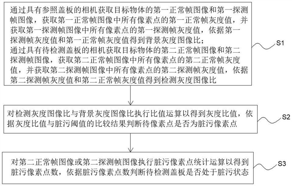
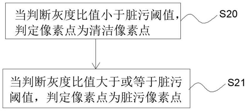
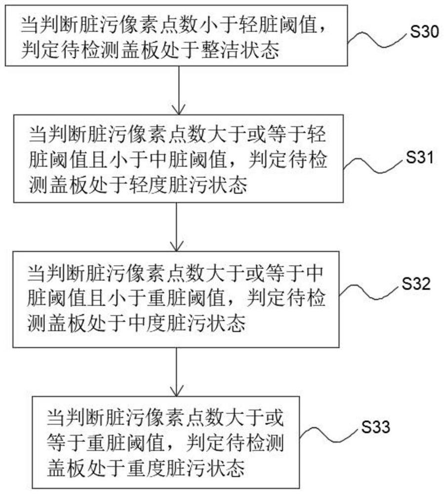
The invention provides a smudginess detection method for a camera cover plate. The smudginess detection method comprises the following steps: acquiring a first normal frame gray value, a first detection frame gray value and a background gray image ratio of a target object through a camera with a reference cover plate; and acquiring a second normal frame gray value, a second detection frame gray value and a detection gray image ratio of the target object through a camera with a to-be-detected cover plate. According to the method, the gray scale ratio is obtained, whether the pixel point is the dirty pixel point is judged according to the comparison result of the gray scale ratio and the dirty threshold value, and whether the cover plate to be detected is in the dirty state is judged according to the number of the dirty pixel points, so that the accuracy and precision of the detection result of the dirty state of the cover plate are improved. The invention further provides a detection device which comprises a laser device, an imaging sensor and a processing module, and the camera cover plate smudginess detection accuracy is improved.

Description

technical field [0001] The invention relates to the field of cameras, in particular to a method and device for detecting contamination of a camera cover. Background technique [0002] Time of Flight (TOF) camera is a new generation of distance detection and 3D imaging technology products. It is by continuously sending light pulses to the target, and then using the sensor to receive the light returned from the object, and the distance of the target object is obtained by detecting the flight (round trip) time of the light pulse. During the working process of the TOF camera, the surface of the cover glass (CG) will gradually accumulate dust, which will cause inaccurate distance measurement. Therefore, there is a need to detect the presence of dust on the surface. [0003] The invention patent with the publication number CN 112672017 A discloses a test structure, a ToF device and a method for detecting lens contamination. The test structure is used to set the light output dire...

Claims


Application Information

Patent Timeline
Patent Type & Authority Applications(China)
IPC IPC(8): G06T7/00H04N17/00G01S7/497G01S17/894
CPCG06T7/0002H04N17/002G01S17/894G01S7/497G01S2007/4975
Inventor 尹睿徐敏张卫金健
Owner SHANGHAI INTEGRATED CIRCUIT MFG INNOVATION CENT CO LTD
Why Eureka
Try Eureka