
Motor stator winding and inserting combined machine

A motor stator and combined machine technology, applied in the direction of electric components, manufacturing motor generators, electrical components, etc., can solve the problems affecting the working efficiency of the winding mechanism, high temperature caused by device friction, friction damage of the winding shaft, etc., to achieve the solution of winding The effect of low efficiency, ensuring safe use, and improving efficiency

Pending Publication Date: 2021-10-26
苏州亚斯特自动化设备有限公司
View PDF1 Cites 0 Cited by
  • Summary
  • Abstract
  • Description
  • Claims
  • Application Information

AI Technical Summary

Problems solved by technology

[0005] But above-mentioned technical scheme still has many shortcomings when practical application;
[0006] 1. Since the reference document uses the winding mechanism to wind a large number of coils when winding the coil, and because the winding mechanism uses devices such as the winding shaft and the bearing shaft to drive the coil to wind the winding, At the same time, long-term continuous winding work is required in the factory, so after the winding mechanism works for a long time, it will cause frictional damage to the winding shaft, thereby affecting the working efficiency of the winding mechanism;
[0007] 2. Since the comparison document uses the rotary mechanism to drive the winding mechanism and other devices to rotate, and the main force in the rotary mechanism is the servo motor. When the rotary mechanism is in use, it uses the rotation of the servo motor to work, so when When the slewing mechanism works for a long time, it will cause high temperature due to the friction of the internal device of the mechanism. At the same time, the high temperature is not well dissipated in the comparison document, so under long-term work, the slewing mechanism will be damaged, which will affect the winding. line efficiency

Method used


Image

  • Motor stator winding and inserting combined machine
  • Motor stator winding and inserting combined machine
  • Motor stator winding and inserting combined machine

Examples


Embodiment Construction

[0026] The following will clearly and completely describe the technical solutions in the embodiments of the present invention with reference to the accompanying drawings in the embodiments of the present invention. Obviously, the described embodiments are only some, not all, embodiments of the present invention. Based on the embodiments of the present invention, all other embodiments obtained by persons of ordinary skill in the art without making creative efforts belong to the protection scope of the present invention.

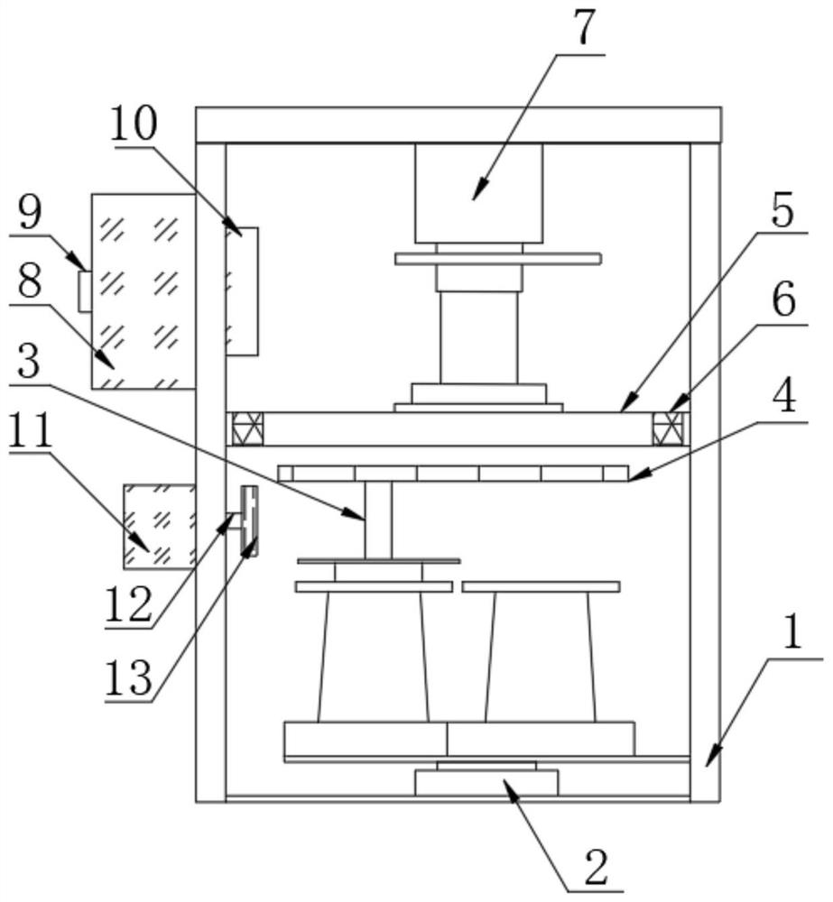
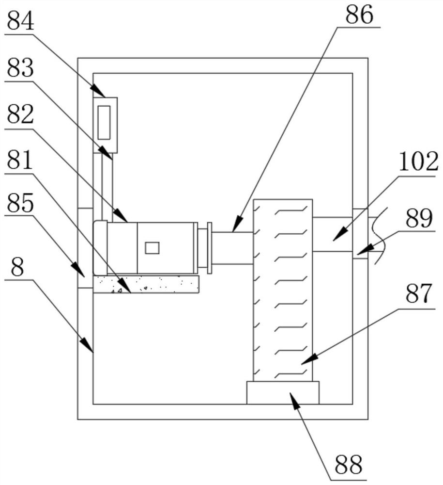
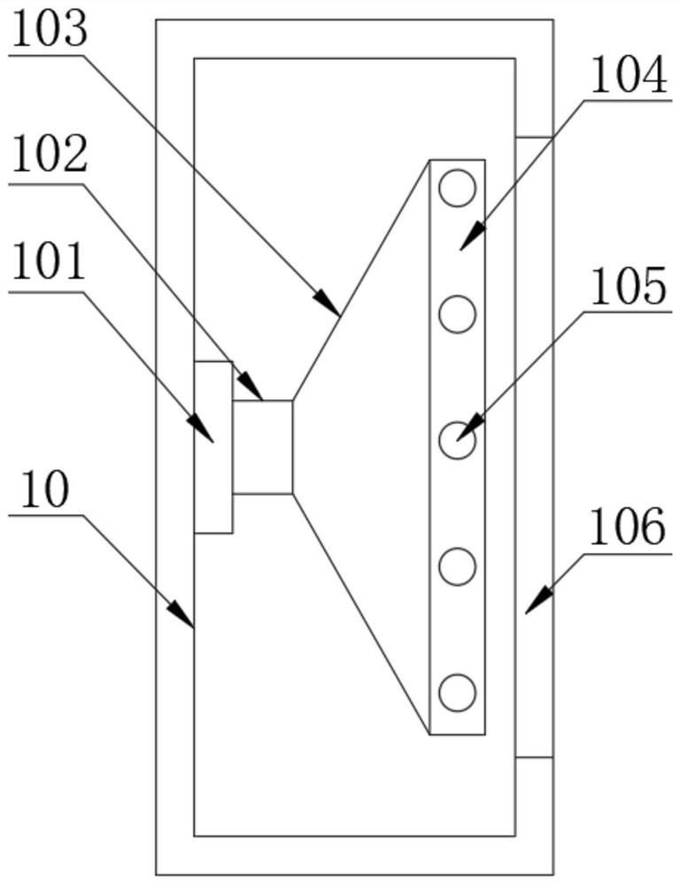
[0027] as attached Figure 1-4 The motor stator winding and embedding combination machine shown includes a frame body 1, a wire carrying mechanism 2, a winding shaft 3, a winding mechanism 4 and a rotary mechanism 7. The middle part of the frame body 1 is welded with a partition 5, and the part of the partition 5 Ventilation grooves 6 are provided on the left and right sides, and the cooling side box 8 is fixedly installed on the top of one side of the frame b...


PUM


Abstract

The invention discloses a motor stator wire winding and inserting combined machine, and particularly relates to the field of motor production equipment. The motor stator wire winding and inserting combined machine comprises a frame body, a wire carrying mechanism, a wire winding shaft, a wire winding mechanism and a swing mechanism. A partition plate is welded in the middle of the frame body, vent grooves are formed in the left side and the right side of the partition plate, and a cooling side box is fixedly mounted at the top of one side of the frame body; the other side of the cooling side box is fixedly sleeved with a dismounting handle, and one side of the cooling side box is fixedly provided with a spraying side plate. By arranging the smearing device, due to the fact that long-time continuous winding work needs to be carried out in a factory, after the winding mechanism works for a long time, the winding shaft can be subjected to friction damage, at the moment, when the winding mechanism works, the smearing device automatically lubricates and smears the winding shaft in a timing mode, damage is prevented, the problem that the winding shaft is damaged is solved, and the winding shaft is prevented from being damaged. And the problem that the working efficiency of the winding mechanism is reduced is solved, so that the safe use of the winding shaft is ensured.

Description

technical field [0001] The invention relates to the technical field of motor production equipment, and more specifically, the invention is a motor stator winding and embedding combination machine. Background technique [0002] When the coils of industrial ventilators, balance cars and large drone motors are wound, they are all processed and produced by stator inserting machines. When the stator inserting machines work, the coils are automatically inserted once according to the winding specifications. If you add auxiliary tools, the embedding efficiency will be greatly improved. [0003] The thread inserting machine has a single thread inserting process, and the number of thread inserts each time is the number of ejector pins. After the thread inserting is completed once, the coil needs to be reinstalled, which cannot realize circular inserting, and the efficiency is low. Its winding and inserting are two machines. Working separately makes it a waste of time to transport the...

Claims


Application Information

Patent Timeline
Patent Type & Authority Applications(China)
IPC IPC(8): H02K15/085
CPCH02K15/085
Inventor 李平
Owner 苏州亚斯特自动化设备有限公司
Learn More