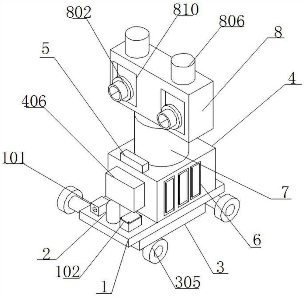
A patrol robot with obstacle avoidance function
A robot and functional technology, applied in manipulators, manufacturing tools, etc., can solve the problems of lack of cleaning structure, lack of anti-dumping function, lack of heat dissipation structure, etc.
- Summary
- Abstract
- Description
- Claims
- Application Information
AI Technical Summary
Problems solved by technology
Method used
Image
Examples
Embodiment 2
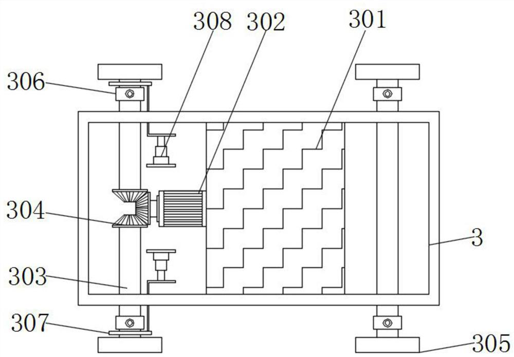
[0043] Example 2: see figure 2 , an embodiment provided by the present invention: a patrol robot with obstacle avoidance function, a battery 301 is installed on the inner wall of the battery box 3, a first motor 302 is installed on the outer wall of the battery 301, and the output end of the first motor 302 is installed There is a No. 1 bevel gear, a plurality of driving rods 303 are installed through the outer wall of the battery box 3, and the other end of the driving rod 303 is installed with a No. 2 bevel gear 304, and the No. 2 bevel gear 304 is meshed with the No. 1 bevel gear, and the driving rod 303 One end of the universal joint 306 is installed with a universal joint 306, one end of the universal joint 306 is installed with an adjustment ring 307, one end of the universal joint 306 is installed with a wheel 305, an L-shaped connecting rod is installed on the outer wall of the adjustment ring 307, and one end of the connecting rod is installed Extending into the inte...
Embodiment 3
[0044] Example 3: see Image 6 and Figure 7 , an embodiment provided by the present invention: a patrol robot with obstacle avoidance function, the inner wall of the horizontal detection box 5 is provided with a sliding track 501, the inner wall of the sliding track 501 is installed with a detection ball 502, and the two sides of the sliding track 501 A trigger switch 503 is installed on the inner wall, a fixing plate 504 is installed on the inner wall of the sliding track 501, an insertion rod 505 is installed through the outer wall of the fixing plate 504, and a return spring is installed around the outer wall of the insertion rod 505. A protective plate 601 is installed on the wall through a bearing, a fixed shaft 602 is installed on the inner rear wall of the protective groove 6, a telescopic tube 603 is installed at the bottom of the fixed shaft 602, a telescopic spring 604 is installed on the inner wall of the telescopic tube 603, and the bottom of the telescopic spring...
Embodiment 4
[0045] Example 4: see Figure 4, an embodiment provided by the present invention: a patrol robot with obstacle avoidance function, the outer wall of the observation box 8 is provided with a rotation groove 810, the inner wall of the observation box 8 is installed with a fixed rotating shaft 801, and the outer wall of the fixed rotating shaft 801 is installed with a The camera head 802, and one end of the camera head 802 extends out of the front of the rotation slot 810, a limit spring 803 is installed on the inner bottom wall of the observation box 8, and the top of the limit spring 803 and the bottom of the camera head 802 are connected by a rotating shaft, and the inner wall of the observation box 8 is connected A fixed pulley 804 is installed, a drive motor 805 is installed on the inner bottom wall of the observation box 8, and a coil is installed around the output end of the drive motor 805, and the coil, the fixed pulley 804 and the camera 802 are connected by cables. A p...
PUM
 Abstract
Description
Claims
Application Information
 - R&D
- Intellectual Property
- Life Sciences
- Materials
- Tech Scout
- Unparalleled Data Quality
- Higher Quality Content
- 60% Fewer Hallucinations
Browse by: Latest US Patents, China's latest patents, Technical Efficacy Thesaurus, Application Domain, Technology Topic, Popular Technical Reports.
© 2025 PatSnap. All rights reserved.Legal|Privacy policy|Modern Slavery Act Transparency Statement|Sitemap|About US| Contact US: help@patsnap.com


