Dynamic implementation method for three-dimensional model of equipment

A 3D model and implementation method technology, applied in 3D modeling, image data processing, special data processing applications, etc., can solve the problems of cumbersome product binding process, inability to timely feedback product changes, etc., to avoid multiple creation processes, Simplifies implementation effort and reduces the effect of configuration errors

Pending Publication Date: 2021-10-29
ZHEJIANG SUPCON INFORMATION TECH CO LTD
View PDF1 Cites 3 Cited by
  • Summary
  • Abstract
  • Description
  • Claims
  • Application Information

AI Technical Summary

Problems solved by technology

[0005] The present invention mainly solves the technical problem that the product binding process of the original technical solution is cumbersome and the product change cannot be fed back in time, and provides a dynamic realization method of the three-dimensional model of the equipment. By configuring the attribute points and associating the attribute points with the dynamic identification, the establishment The device model, the background service stores dynamic identifiers and attribute value association information. The information includes attribute points, state identifiers associated with expressions, and interfaces for obtaining attribute point values. At the same time, the occurrence of configuration errors is reduced. Later, specific devices can be associated Obtain the device attribute point value on the page and call the 3D engine to load and display the 3D model, update the 3D dynamic effect diagram in real time through the attribute point value and status identification association relationship information, and the same device can reuse product data and 3D models, avoiding the traditional The multiple creation process of products and 3D models in the monitoring system greatly simplifies the implementation workload

Method used


Image

  • Dynamic implementation method for three-dimensional model of equipment
  • Dynamic implementation method for three-dimensional model of equipment
  • Dynamic implementation method for three-dimensional model of equipment

Examples


Embodiment

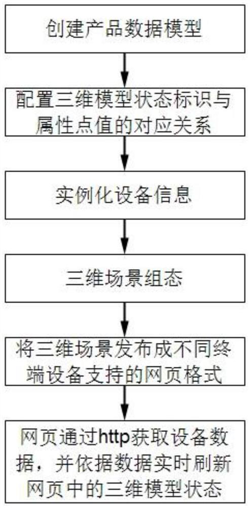
[0037] Embodiment: A method for dynamically realizing a three-dimensional model of equipment in this embodiment, such as figure 1 shown, including

[0038] Step 1: Product data modeling, that is, abstract product attribute points

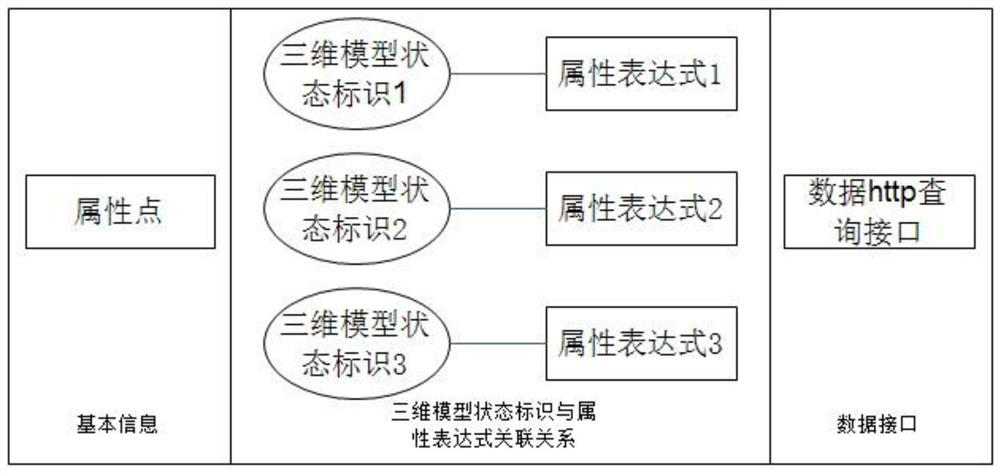
[0039] In the central control Internet of Things platform, the present invention summarizes and organizes devices of the same type into abstract device templates, that is, products. Each attribute parameter is set as an attribute point of the product, and each attribute point includes related parameters such as attribute name, value type (Boolean quantity, data quantity and string quantity) and attribute description. Product information is stored in JSON structure.

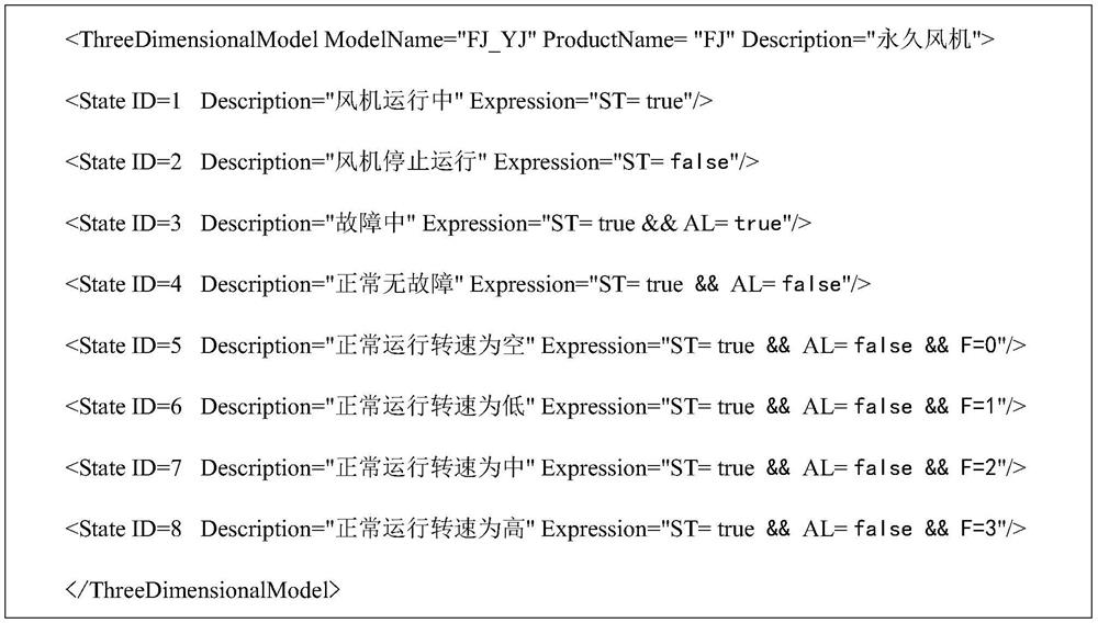
[0040] Taking a common fan in the project as an example, the fan product is named FJ, and the data of the fan product is modeled, that is, the attribute point parameters of the fan product are configured:

[0041] 1. The start and stop status of the fan, attribute name: ST, indicatin...


PUM


Abstract

The invention discloses a dynamic implementation method for a three-dimensional model of equipment. The method comprises the following steps: carrying out product data modeling; establishing an association relationship between the three-dimensional model state identifier and the attribute value; instantiating the equipment according to the product data model; carrying out three-dimensional model space position configuration and binding with a device ID; publishing the three-dimensional scene into pages supported by different equipment terminals; and monitoring, updating and displaying the real-time state of the three-dimensional model in the web page. According to the technical scheme, the attribute points are configured, the attribute points are associated with the dynamic identifiers, the equipment model is established, the background service stores the association relationship information of the dynamic identifiers and the attribute values, and the information comprises the attribute points, the state identifiers associated with the expressions and the interfaces for obtaining the attribute point values; and meanwhile, configuration errors are reduced, and subsequently, the three-dimensional model can be loaded and displayed by associating specific equipment to obtain equipment attribute point values on the page and calling a three-dimensional engine.

Description

technical field [0001] The invention relates to the technical field of three-dimensional virtual reality, in particular to a method for dynamically realizing a three-dimensional model of equipment. Background technique [0002] In the past monitoring platform, only 3D models customized by the monitoring platform or very few types can be identified, and 3D model types from other manufacturers in the market cannot be loaded or dynamic effects cannot be displayed. 3D model dynamics are often directly bound to device attribute points to achieve 3D dynamic effects. Even for devices of the same product, due to the difference in the naming of device attribute points, the binding operation needs to be repeated many times. The process is more cumbersome and error-prone. [0003] According to data, with the development of Internet technology, the monitoring platform is gradually moving towards the Internet, and the monitoring pages must also support different device terminals at the ...

Claims


Application Information

Patent Timeline
Patent Type & Authority Applications(China)
IPC IPC(8): G06F16/81G06F16/9538G06T17/00
CPCG06F16/81G06F16/9538G06T17/00
Inventor 杨振伟王陈淼林杨平唐飞婷姜雪明戴强
Owner ZHEJIANG SUPCON INFORMATION TECH CO LTD
Why Eureka
Try Eureka