Multifunctional sports basketball training device
A training device and multi-functional technology, which can be applied to ball games, sports accessories, etc., can solve the problems that trainers cannot complete passing training, and there is no overall passing training device, and achieve novel mechanism, good training effect, and training mode. many effects
- Summary
- Abstract
- Description
- Claims
- Application Information
AI Technical Summary
Problems solved by technology
Method used
Image
Examples
Embodiment 1
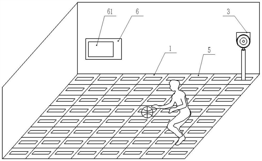
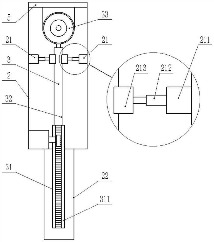
[0053] Such as figure 1 Shown, a kind of multifunctional sports basketball training device comprises a plurality of floor tile training blocks 1 evenly laid on the training field, wherein, as figure 2 As shown, each floor tile training block 1 includes an empty slot 2, a holding and fixing mechanism 21, a training target mechanism 3, a lifting motor 4, a floor tile lamp 5 and a controller 6. Wherein, the empty slot 2 is set inside the training field; the training target mechanism 3 is movably arranged in the empty slot 2, including: a gear bar 31 with a rack 311 on the side, a target bar 32 that is rotationally connected to the upper end of the rack bar 31, and a rotationally connected The training target 33 on target bar 32 upper ends, as Figure 7 As shown, the target rod 32 includes: a lower rod 321, located at the bottom of the target rod 32, the lower end of the lower rod 321 is fixedly connected to the surface of the rotating shaft 342; an upper rod 322, located at the...
Embodiment 2
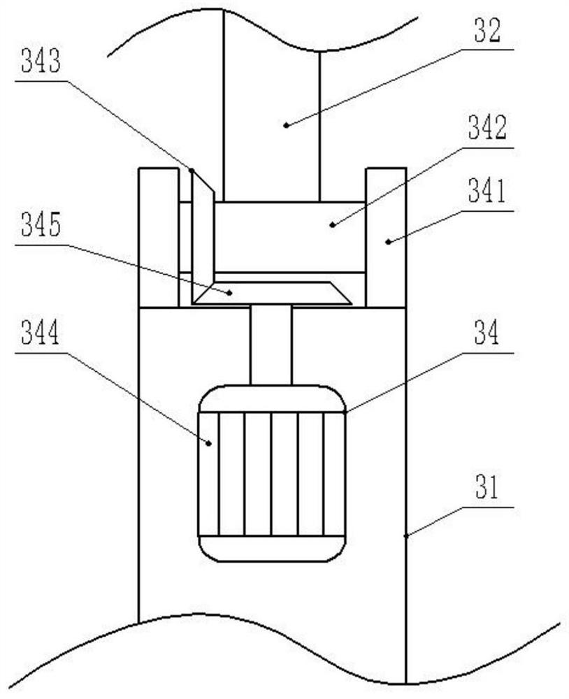
[0055] The difference from Embodiment 1 is that in order to solve the problem that the swing position of the training target 33 in Embodiment 1 cannot be adjusted, a swing mechanism 34 is provided at the joint between the gear rod 31 and the target rod 32, such as image 3 As shown, the swing mechanism 34 includes a bearing seat 341 , a rotating shaft 342 , a first bevel gear 343 and a driving motor 344 . Among them, the bearing seat 341 is symmetrically and fixedly arranged on the upper end of the gear rod 31; the rotating shaft 342 is rotatably connected between the two bearing seats 341, and the lower part of the target rod 32 is fixedly connected with the middle part of the rotating shaft 342; the first bevel gear 343 is fixedly sleeved on the The outer side of the rotating shaft 342; the driving motor 344 is arranged inside the upper end of the gear rod 31 and is connected with the controller 6. The output shaft at the upper end of the driving motor 344 is provided with a ...
Embodiment 3
[0057] The difference from embodiment 2 is that although the swing position of the training target 33 can be adjusted in embodiment 2, the rotation angle of the training target 33 cannot be adjusted. In order to rotate the angle of the training target 33 and simulate the passing position at different angles, A rotating mechanism 35 is provided at the connection between the training target 33 and the target rod 32, such as Figure 4 As shown, the rotating mechanism 35 includes a rotating motor 351 , a rotating shaft 352 and a limit bearing 353 . Wherein, the rotating motor 351 is arranged inside the upper rod 322 and is connected with the controller 6; the rotating shaft 352 is fixedly connected to the upper output end of the rotating motor 351, and the upper end of the rotating shaft 352 is fixedly connected to the bottom of the training target 33; the limit bearing 353 is arranged on The upper end of the upper rod 322 is sleeved on the outside of the rotating shaft 352 for li...
PUM
 Abstract
Description
Claims
Application Information
 - R&D Engineer
- R&D Manager
- IP Professional
- Industry Leading Data Capabilities
- Powerful AI technology
- Patent DNA Extraction
Browse by: Latest US Patents, China's latest patents, Technical Efficacy Thesaurus, Application Domain, Technology Topic, Popular Technical Reports.
© 2024 PatSnap. All rights reserved.Legal|Privacy policy|Modern Slavery Act Transparency Statement|Sitemap|About US| Contact US: help@patsnap.com


