
Clamping and vibrating device for plastic-dipped bearing retainer

A bearing retainer and vibration device technology, which is applied to the surface coating liquid device, coating, etc., can solve the problems of loose clamping, poor vibration effect of the cage, and increased work difficulty.

Inactive Publication Date: 2021-11-02
SHANDONG GOLDEN EMPIRE PRECISION MACHINERY TECH CO LTD
View PDF15 Cites 0 Cited by
  • Summary
  • Abstract
  • Description
  • Claims
  • Application Information

AI Technical Summary

Problems solved by technology

[0003] However, during the dipping process of the bearing cage, when the cage is taken out of the plastic powder, the plastic powder on the surface close to the metal surface tends to melt and shape, and the closer to the outside of the plastic powder, because the temperature of the cage itself Weakened, resulting in the outer plastic powder cannot be completely melted into the plastic layer, at this time it is necessary to remove the outer plastic powder as soon as possible, so that the thickness of the plastic layer after molding is uniform, so as to avoid affecting the quality of the plastic layer, currently limited by the clamping tooling, the vibration effect of the cage Poor, the excess plastic powder cannot be removed in time, which increases the difficulty of subsequent processing, and the vibration structure is unreliable, which can easily lead to loose clamping, and the vibration process needs to consume more energy, which needs to be solved urgently

Method used


Image

  • Clamping and vibrating device for plastic-dipped bearing retainer
  • Clamping and vibrating device for plastic-dipped bearing retainer
  • Clamping and vibrating device for plastic-dipped bearing retainer

Examples


Embodiment Construction

[0028] In order to have a clearer understanding of the technical features, purposes and effects of the present invention, the specific embodiments of the present invention will now be described with reference to the accompanying drawings, in which the same reference numerals represent components with the same or similar structures but the same functions.

[0029] In the following description, many specific details are set forth in order to fully understand the present invention. However, the present invention can also be implemented in other ways different from those described here. Therefore, the protection scope of the present invention is not limited by the specific details disclosed below. EXAMPLE LIMITATIONS.

[0030] Just like the background technology, currently limited by the clamping tooling, the vibration effect of the cage is poor, resulting in the excess plastic powder not being removed in time, increasing the difficulty of subsequent processing, and the vibration s...


PUM


Abstract

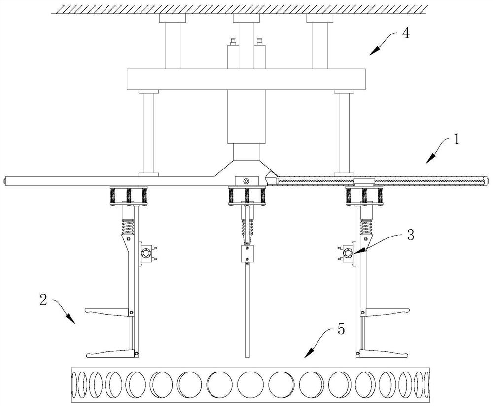
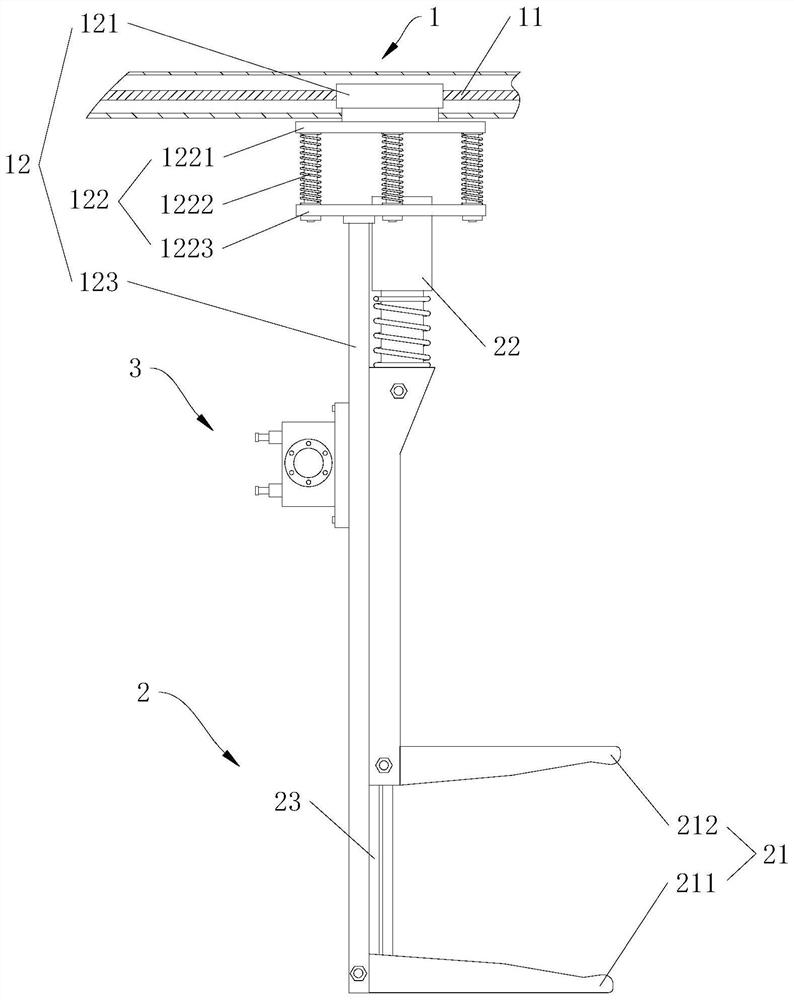
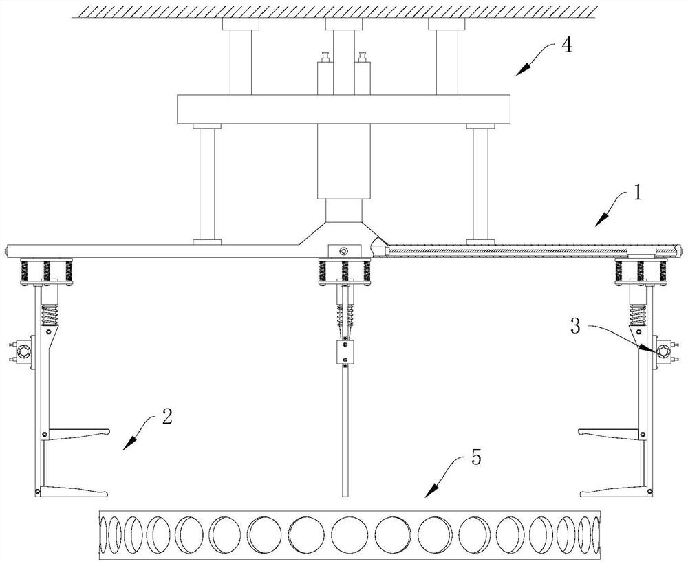
The invention discloses a clamping and vibrating device for a plastic-dipped bearing retainer. The clamping and vibrating device for the plastic-dipped bearing retainer comprises a radial moving mechanism, a clamping mechanism, vibrators and an axial lifting mechanism, wherein the radial moving mechanism comprises a driving part and at least three moving parts, and the driving part drives the moving parts to move along the radial direction of the retainer; the clamping mechanism comprises at least three clamping parts, and the clamping parts are connected with the moving parts and used for clamping the retainer; the vibrators are arranged on the clamping parts or the moving parts so as to vibrate the retainer; and the axial lifting mechanism is arranged above the radial moving mechanism and connected with the radial moving mechanism so as to drive the retainer to move in the vertical direction. According to the invention, redundant outer-side molding powder on the retainer can be removed, so that a plastic layer of the retainer is uniform, flat and firm.

Description

technical field [0001] The invention relates to the technical field of bearing retainers, in particular to a clamping vibration device for a plastic dipped bearing retainer. Background technique [0002] The cage (that is, the bearing cage, also known as the bearing cage) refers to the bearing parts that partially wrap all or part of the rolling elements and move with them, to isolate the rolling elements, and usually guide the rolling elements and keep them in the bearing Inside. When the rolling bearing is working, especially when the load is complex and rotates at high speed, the cage has to bear a lot of centrifugal force, shock and vibration, there is a large sliding friction between the cage and the rolling elements, and a lot of heat is generated. The result of the combined action of force and heat can lead to failure of the cage, and in severe cases, it will cause burns and fracture of the cage. Therefore, the cage material is required to have good thermal conducti...

Claims


Application Information

Patent Timeline
IPC IPC(8): B05C13/02
CPCB05C13/02
Inventor 郑广会
Owner SHANDONG GOLDEN EMPIRE PRECISION MACHINERY TECH CO LTD
Learn More