A robotic clamping device

A clamping device and robot technology, applied in the direction of chucks, manipulators, manufacturing tools, etc., can solve the problems of clamping device action and joint rotation not flexible enough, application level is difficult to play, and clamping force is small, etc., to achieve easy Operation and maintenance, easy processing, strong clamping effect

Active Publication Date: 2017-09-01
佛山市慧智智能装备有限公司
View PDF5 Cites 0 Cited by
  • Summary
  • Abstract
  • Description
  • Claims
  • Application Information

AI Technical Summary

Problems solved by technology

However, with the popularity of robots, the clamping devices used by robots are subject to many restrictions due to their shortcomings such as inflexible movements and joint rotations, complex structures, high manufacturing costs, and low clamping force, especially in the welding industry. Its application level is difficult to give full play to its due advantages

Method used


Image

  • A robotic clamping device
  • A robotic clamping device
  • A robotic clamping device

Examples


Embodiment 1

[0026] This embodiment takes the clamping arm as an example with a two-layer structure to describe the following.

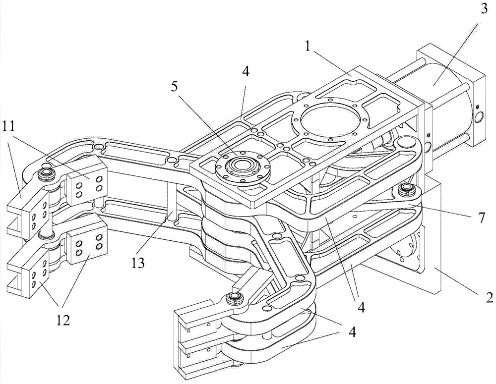
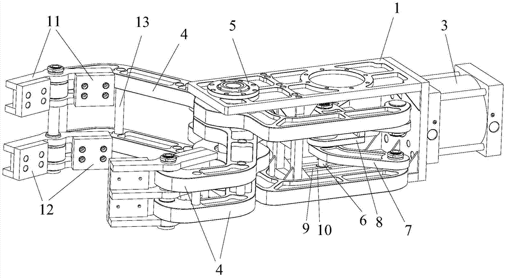
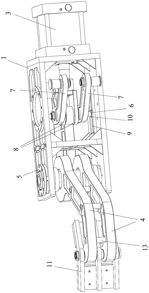
[0027] like figure 1 , figure 2 and image 3 As shown, the robot clamping device of the present invention is installed on the front end of the mechanical arm of the robot for clamping the workpiece; the clamping device includes a main frame 1, a connecting seat 2 for connecting with the front end of the mechanical arm, and The connection mechanism inside the frame 1, the driving mechanism 3 for driving the movement of the connection mechanism, the control mechanism and the clamping arm 4; wherein, the connecting seat 2 is arranged on the main frame 1, and the two clamping arms 4 are arranged on the main frame in a cross form. Both sides of the frame 1, and one end is hinged with the connecting mechanism. The intersection is the connecting shaft 5 arranged at the front end of the main frame 1, and the two clamping arms 4 are rotatably connected to the connecti...

Embodiment 2

[0034] The only difference between this embodiment and Embodiment 1 is that the two clamping arms can be set to a single-layer structure, a three-layer structure or a structure with more than three layers, and in the clamping arms with a three-layer structure or a structure with more than three layers , each structure is connected by connecting rods. The design of the multi-layer structure of the clamping arm can increase the contact area between the clamping arm and the workpiece, thereby further improving the clamping force of the clamping device.

[0035] Other structures of this embodiment are consistent with Embodiment 1.


PUM


Abstract

The invention provides a clamping device for a robot, which includes a main frame, a connecting seat for connecting with the front end of a mechanical arm, a connecting mechanism arranged inside the main frame, a driving mechanism for driving the connecting mechanism to move, a control mechanism and a clamping mechanism. The connecting seat is set on the main frame; the two clamping arms are set on both sides of the main frame in the form of a cross, and one end is hinged with the connecting mechanism; the intersection is set on the main frame, and the two clamping arms are connected to the cross The connection can be rotated; the driving mechanism is connected with the control mechanism by signal, so as to realize the movement of the driving connection mechanism to drive the opening and closing movement of the clamping arm. The clamping device of the present invention has high action flexibility and strong clamping force, thereby realizing fast grabbing and stable and reliable clamping of workpieces, and greatly improving production efficiency and automation when used in conjunction with robots. The clamping device of the present invention has a simple structure, thereby making the device easy to operate and maintain, and reducing its use cost.

Description

technical field [0001] The invention relates to the technical field of welding processing machinery, and more specifically, relates to a robot clamping device. Background technique [0002] In the mechanical processing and welding processing industries, objects are often grasped and positioned. This operation is generally simple and highly repeatable. In view of the above situation, robots that can replace manpower and work automatically solve this problem better. Robots are widely used in the industrial field to improve production processes, shorten processing time, improve manufacturing accuracy, and greatly save labor costs. [0003] In the specific use process of the robot, the clamping device is usually installed on the front end of the robot's mechanical arm, and the object is clamped by the gripper driven by the cylinder to complete the grasping process, and then the clamped object is manufactured and processed on the production line or processing line . However, w...

Claims


Application Information

Patent Timeline
Patent Type & Authority Patents(China)
IPC IPC(8): B25J15/08
Inventor 卢新建陈飞龙陈先松
Owner 佛山市慧智智能装备有限公司
Why Eureka
Try Eureka