Two-degree-of-freedom humanoid ankle joint

An ankle joint, degree of freedom technology, applied in the direction of motor vehicles, transportation and packaging, can solve the problems of difficult control, increased swing inertia of the ankle joint, and complicated ankle structure due to the driving mechanism and driving method, so as to improve the movement of the ankle. Flexibility, improved anthropomorphism, high similarity effects

Inactive Publication Date: 2013-03-27
ZHENGZHOU UNIVERSITY OF LIGHT INDUSTRY
View PDF5 Cites 14 Cited by
  • Summary
  • Abstract
  • Description
  • Claims
  • Application Information

AI Technical Summary

Problems solved by technology

[0003] At present, there are many kinds of ankle joint structures of humanoid robots. The early humanoid robot 2-degree-of-freedom ankle joints generally adopt the arrangement of two joint axis spaces perpendicular to each other and serial drive, mainly Ohio University and National University of Defense Technology. , Harbin Institute of Technology, the degree of freedom configuration of this mechanism and its driving method are simple, but the driving motor of the ankle joint and its deceleration device increase the swing inertia of the leg, making it difficult to control and it is difficult to achieve fast walking
At present, the ankle joints of most humanoid robots represented by ASIMO adopt a Hooke hinge mechanism with 2 degrees of freedom. The two joint axes of the forward swing and side swing of the mechanism are perpendicular to each other. The robot with this degree of freedom configuration often uses a harmonic reducer. (or with synchronous belt) fixed transmission ratio device, its driving mechanism and driving method make the structure of the ankle complex

Method used


Image

  • Two-degree-of-freedom humanoid ankle joint
  • Two-degree-of-freedom humanoid ankle joint
  • Two-degree-of-freedom humanoid ankle joint

Examples


Embodiment Construction

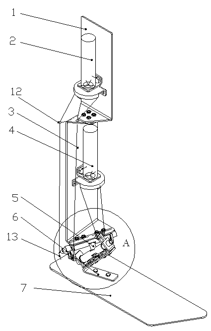
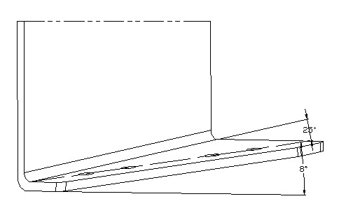
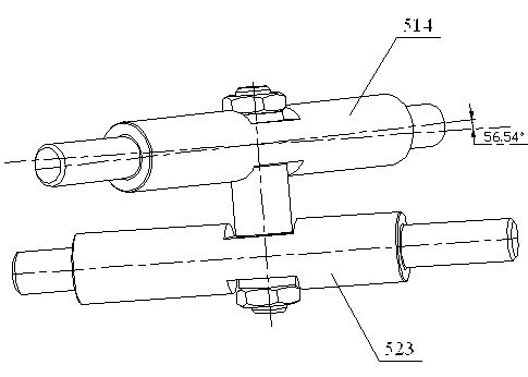
[0020] to combine Figure 1-9 , the present invention is composed of calf upper part 1, calf lower part 3, driving device I2, driving device II4, double joint member 5, bending bracket 6, foot 7, and driving brake line; calf upper part 1 and calf lower part 3 are flange parts , between the upper leg 1 and the lower leg 3 are connected by bolts, such as figure 1 and Figure 9 shown. The 3-fold bending angle of the lower leg ensures that the included angle between the ankle joint axis 514 and the frontal plane is 25°, and the included angle with the horizontal plane is 8°, for example figure 2 shown. The ankle joint axis 514 and the subtalar joint axis 523 are secured by screws to ensure that the included angle is 56.54° and the distance is 20 mm, as image 3 shown. The subtalar joint axis 523 is installed on the bending bracket 6, and the bending angle of the bending bracket 6 and its installation direction angle on the foot 7 ensure that the included angle between the su...


PUM


Abstract

The invention discloses a two-degree-of-freedom humanoid ankle joint. The two-degree-of-freedom humanoid ankle joint comprises a upper shank part, a lower shank part, a driving device I, a driving device II, a double-jointed component, a foot and a brake cable; the double-jointed component comprises an ankle joint driving device and a subtarlar joint driving device; the ankle joint driving device comprises an ankle joint shaft; the subtarlar joint driving device comprises a subtarlar joint shaft; the ankle joint comprises an upper shaft and a lower shaft, wherein the upper shaft is the ankle joint shaft, and the lower shaft is the subtarlar joint shaft; and the ankle joint shaft and the subtarlar joint shaft are in space cross, and the axes of the ankle joint shaft and the subtarlar joint shaft are not in the same plane. The two-degree-of-freedom humanoid ankle joint provided by the invention can be used for a humanoid robot and improves the personification of a humanoid robot. The mechanism can achieve three movement angles by controlling two parameters, namely, the space two-degree-of-freedom mechanism approximately achieves the three-degree-of-freedom movement of the ankle joint and improves the flexibility of the movement.

Description

technical field [0001] The invention relates to a component structure of a robot, in particular to a two-degree-of-freedom humanoid ankle joint. Background technique [0002] In recent years, robot technology has developed very rapidly, and robots have been widely used in industry, agriculture, service, medical treatment, military and other fields. As one of the most cutting-edge issues in the field of robotics research, the biped walking robot that simulates human walking integrates multiple disciplines such as machinery, control, and artificial intelligence, reflecting the level of intelligence and automation research in a country. The ankle joint is a key component of a biped robot, and its flexibility and anthropomorphism largely determine the walking flexibility and anthropomorphism of a biped robot. Therefore, it is of great significance to design the ankle joint of a biped robot with high anthropomorphism and good flexibility. [0003] At present, there are many kin...

Claims


Application Information

Patent Timeline
Patent Type & Authority Applications(China)
IPC IPC(8): B62D57/032
Inventor 陈鹿民王才东王新杰刘洁陈仁涛陈震王辉
Owner ZHENGZHOU UNIVERSITY OF LIGHT INDUSTRY
Why Eureka
Try Eureka