
A Vibration Measuring Device and Its Digital Twin Method for Multi-size Outline Rotors of Engines

A multi-size, engine technology, applied in the direction of engine testing, measuring device, machine/structural component testing, etc., can solve the problems of inaccurate placement of magnetic meter seats, cumbersome angles, measurement errors, etc., and achieve small axial spacing. Intensive arrangement to solve, avoid repetitive adjustments, and solve the effect of time-consuming problems

Active Publication Date: 2022-05-17
NORTHEASTERN UNIV LIAONING
View PDF9 Cites 0 Cited by
  • Summary
  • Abstract
  • Description
  • Claims
  • Application Information

AI Technical Summary

Problems solved by technology

By changing the structure design of the sensor bracket in the vibration measurement technology, it solves the tediousness of repeated debugging distance and angle. Due to the limitation of the volume of the magnetic meter seat itself, the existing vibration measurement technology cannot realize the dense arrangement of infrared displacement sensors with small spacing in the axial direction of the rotor. There are measurement errors caused by inaccurate placement of the magnetic base in the vibration measurement technology, and the difficulty in positioning the small angle offset or small distance offset that occurs when the magnetic base is finally locked.

Method used


Image

  • A Vibration Measuring Device and Its Digital Twin Method for Multi-size Outline Rotors of Engines
  • A Vibration Measuring Device and Its Digital Twin Method for Multi-size Outline Rotors of Engines
  • A Vibration Measuring Device and Its Digital Twin Method for Multi-size Outline Rotors of Engines

Examples


Embodiment Construction

[0040] In order to more clearly illustrate the technical solutions in the embodiments of the present invention or the prior art, the following will briefly introduce the drawings that need to be used in the description of the embodiments or the prior art. Obviously, the accompanying drawings in the following description These are some embodiments of the present invention. Those skilled in the art can also obtain other drawings based on these drawings without creative work.

[0041] It should be noted that in the description of the present invention, the terms "upper", "lower", "top", "bottom", "side", "other side", "left", "right" etc. indicate The orientation or positional relationship is based on the orientation or positional relationship shown in the drawings, and is only for the convenience of describing the present invention and simplification of the description, and does not mean that devices or elements must have a specific orientation, be constructed and operated in a s...


PUM


Abstract

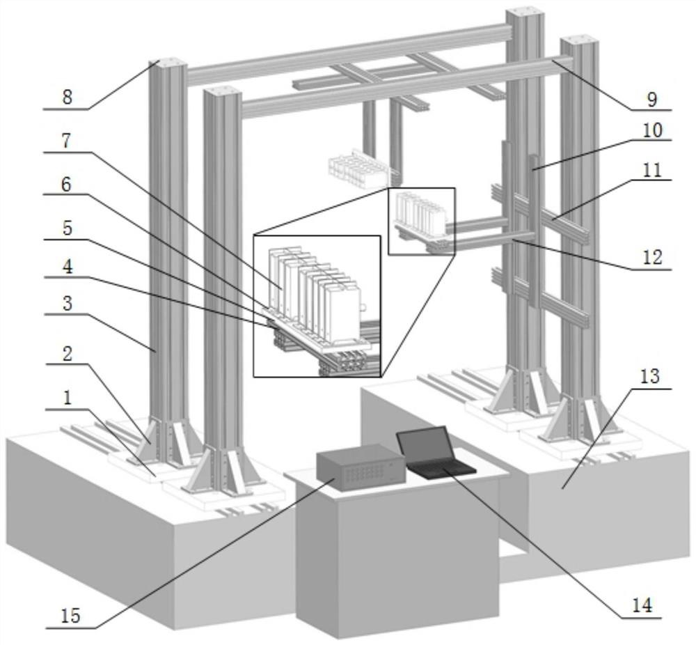
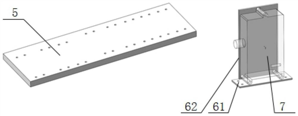
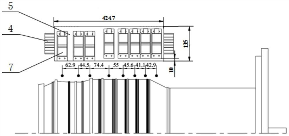
The invention relates to a vibration measuring device and a digital twinning method for an engine multi-size outer profile rotor. The device includes a vibration measuring component and a data acquisition component; the vibration measuring component includes a column, a beam structure, and a three-degree-of-freedom sensor bracket An adjustment mechanism and a base; the data acquisition component includes a test computer, an LMS test system, an infrared displacement infrared displacement sensor, a rotary encoder and a USBCAN device. The invention can solve the cumbersomeness of repeatedly adjusting the distance and angle. Due to the volume limitation of the magnetic meter seat itself, the existing vibration measurement technology cannot realize the dense arrangement of infrared displacement sensors with small spacing in the axial direction of the rotor. The magnetic meter seat swings in the existing vibration measurement technology The problem of measurement error caused by inaccurate placement and the difficulty in positioning of small angle offsets or small distance offsets when the magnetic meter base is finally locked. And the digital twin technology is applied to the test of the rotor of the aero-engine to improve the advancement of the vibration measurement technology of the rotor of the aero-engine.

Description

technical field [0001] The invention relates to the technical field of aero-engine testing, in particular to a vibration measuring device and a digital twinning method for an engine multi-size profile rotor. Background technique [0002] The existing vibration measurement technology is mainly a vibration measurement device composed of a distance regulator, an infrared displacement sensor fixer, etc., plus an infrared distance infrared displacement sensor and a data collector to form a vibration measurement system, which is widely used in machine tool shafts and Engine rotor or other rotating machinery vibration testing occasions. Existing distance regulators are generally composed of magnetic gauge bases and fixing bolts, such as the distance demodulator disclosed in patent document CN104776987A. Most of the existing vibration measuring devices are fixed on the base with a magnetic base, on which the slide rail is fixed by bolts, the sensor bracket is fixed by two bolts at ...

Claims


Application Information

Patent Timeline
Patent Type & Authority Patents(China)
IPC IPC(8): G01M15/02G01H1/00G01B11/02G06F30/20
CPCG01M15/02G01H1/006G01B11/02G06F30/20
Inventor 罗忠刘凯宁李雷刘家希孙凯石宝龙
Owner NORTHEASTERN UNIV LIAONING
Learn More