Automatic code generation method based on synchronous reaction type component

An automatic generation and reactive technology, applied in the field of code generation, can solve problems such as unfavorable maintenance work, code redundancy, and poor readability, so as to reduce development and maintenance costs, reduce coding work, and improve reliability.

Pending Publication Date: 2021-11-02
NORTHWESTERN POLYTECHNICAL UNIV
View PDF0 Cites 0 Cited by
  • Summary
  • Abstract
  • Description
  • Claims
  • Application Information

AI Technical Summary

Problems solved by technology

[0003] However, this method has certain limitations in model building and code generation.
First of all, although the proposed workflow model can well describe the calls between methods or the transfer of messages between objects, it cannot fully represent the branches, loops, nesting and other structures in the control process, and focuses on establishing a complete workflow model for Web applications. It is not suitable for modeling embedded control systems, because the control execution process of embedded systems is generally divided into four parts: environment perception, data processing, decision selection, and control execution. An automatic periodic execution process does not require additional human intervention; secondly, the code generated by the proposed code generation method is redundant, the structure is not clear enough, the readability is poor, and it cannot be executed periodically, and the amount of code is large, which is not conducive to subsequent Maintenance work, at the same time, the consistency between the model and the code cannot be guaranteed, the quality of the generated code cannot be guaranteed, and the code requirements of the embedded system cannot be met

Method used


Image

  • Automatic code generation method based on synchronous reaction type component
  • Automatic code generation method based on synchronous reaction type component
  • Automatic code generation method based on synchronous reaction type component

Examples


Embodiment Construction

[0084] In order to make the object, technical solution and advantages of the present invention clearer, the present invention will be further described in detail below in conjunction with the accompanying drawings and embodiments. It should be understood that the specific embodiments described here are only used to explain the present invention, not to limit the present invention. In addition, the technical features involved in the various embodiments of the present invention described below may be combined with each other as long as they do not conflict with each other.

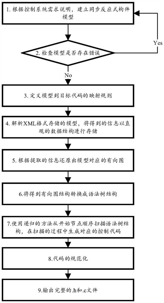
[0085] refer to figure 1 , the present invention proposes a method for automatically generating code based on synchronous reactive components: define the framework of synchronous reactive component models, establish corresponding synchronous reactive component models according to the requirements of the control system; check whether there are errors in the synchronous reactive component models , if there is...


PUM


Abstract

The invention relates to an automatic code generation method based on a synchronous reaction type component, which comprises the following steps: defining a framework of a synchronous reaction type component model, and establishing a corresponding synchronous reaction type component model according to requirements of a control system; checking whether errors exist in the model or not, and if yes, continuing to perfect the model according to the requirements of the control system; defining a mapping rule from the model to a target language; analyzing the model stored in the XML format, and storing the obtained information in a visual data structure; restoring a directed graph corresponding to the model according to the extracted information; since the overall structure of the code to be generated is sequential, converting a directed graph obtained according to the information into a syntax tree structure; scanning the syntax tree from a starting node by adopting a recursion method, and generating a corresponding control code at the same time; in order to ensure the readability of the codes, normalizing the codes; and finally, outputting complete. H and. C files. The invention is suitable for software development of the embedded control system.

Description

technical field [0001] The invention belongs to the technical field of code generation, and in particular relates to a code generation method for a synchronous reactive component. Background technique [0002] The document "Automatic code generation using unified modeling language activity and sequence models, 164 (2016)" discloses a method for generating Java code from a workflow model, which is represented as a set of UML (Unified Modeling Language) activity diagrams and sequence diagrams, Because the UML model alone is not enough to generate complete code, for example, the activity diagram alone cannot give implementation details such as object interaction, so an association relationship is defined between the activity diagram and the sequence diagram to add objects to the workflow Interaction details. Using the idea of ​​Model-Driven Architecture (MDA) to generate code, software design is independent of implementation details and can be implemented on any platform. All...

Claims


Application Information

Patent Timeline
IPC IPC(8): G06F8/41
CPCG06F8/447G06F8/42
Inventor 董云卫李小虎苟倩文李正
Owner NORTHWESTERN POLYTECHNICAL UNIV
Why Eureka
Try Eureka