Teaching demonstration device for chemical industry
A demonstration device and chemical engineering technology, which is applied in the field of chemical engineering teaching, can solve the problems of less obvious comparison of experimental phenomena, reduce the teaching efficiency of teachers, and experimental accidents, so as to achieve better teaching effects, relieve teaching pressure, and improve adaptability
- Summary
- Abstract
- Description
- Claims
- Application Information
AI Technical Summary
Problems solved by technology
Method used
Image
Examples
Embodiment 1
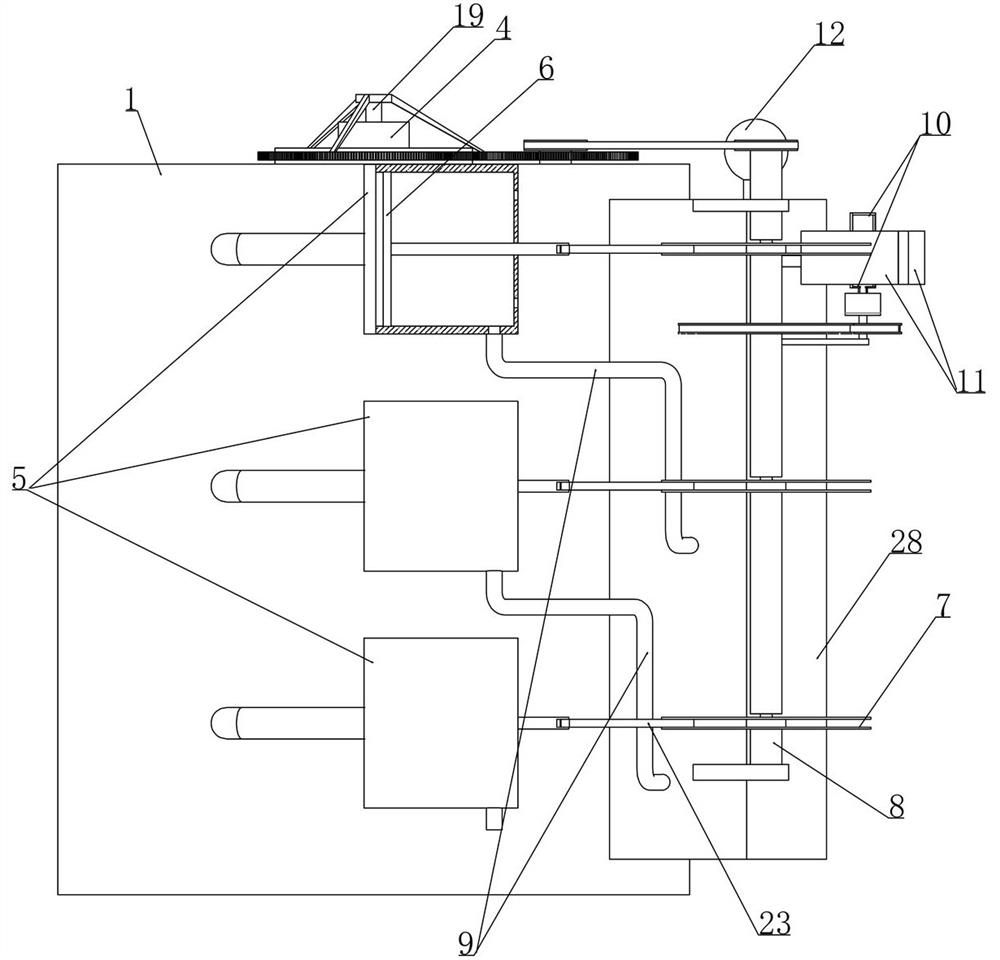
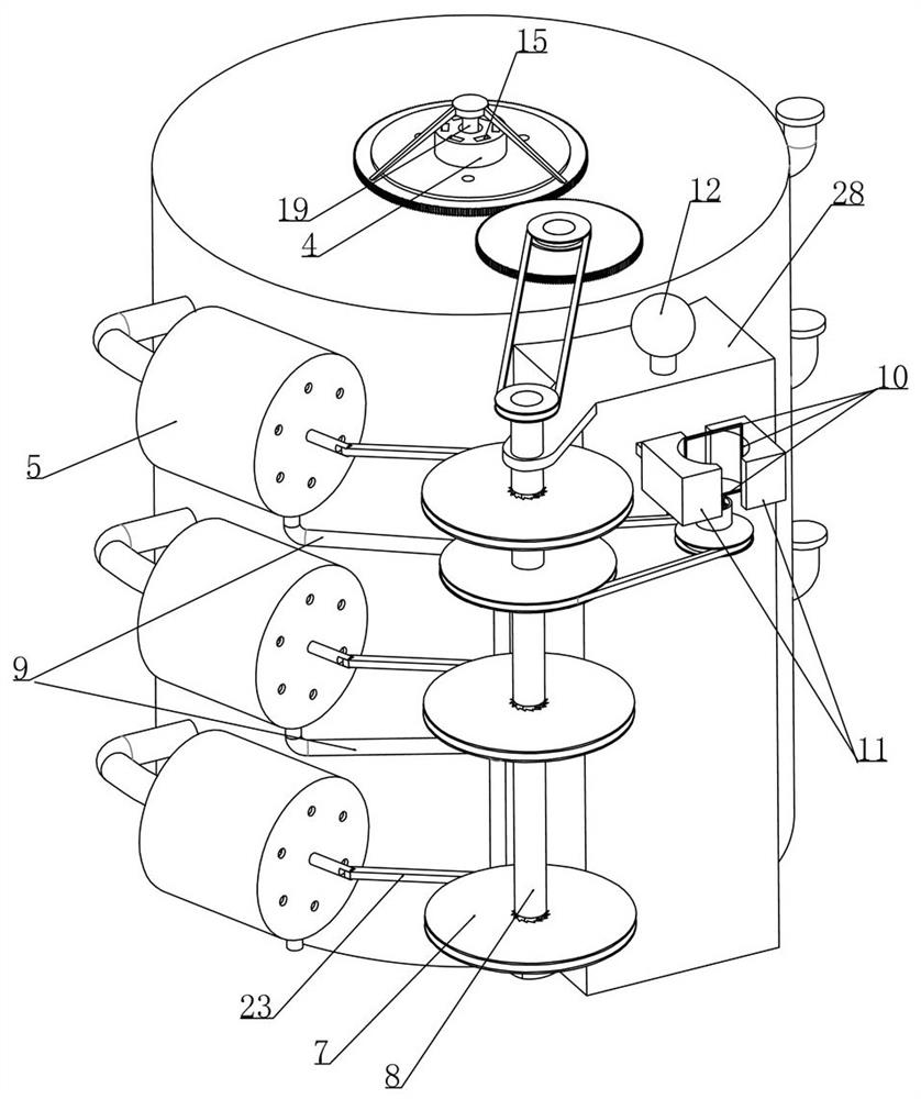
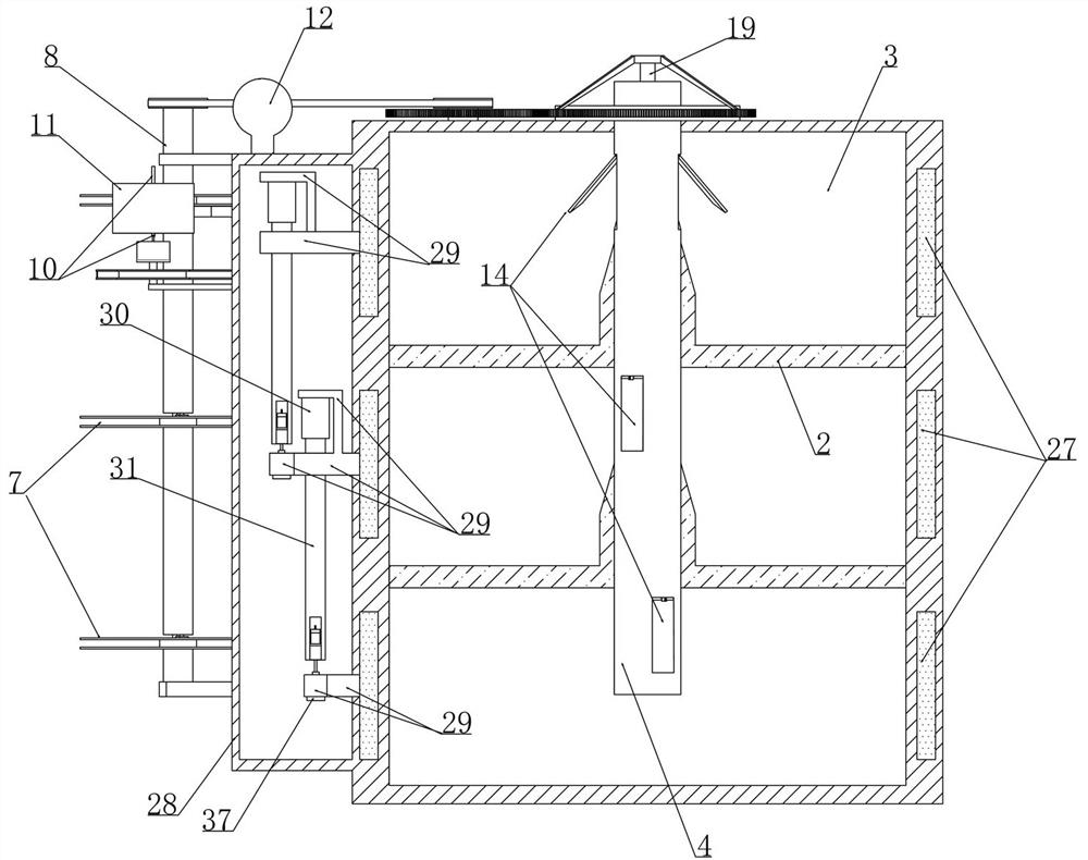
[0028] Embodiment 1, a kind of chemical engineering teaching demonstration device, as attached figure 1 As shown, it includes a cylinder 1 (providing a reaction space for chemical reactions) and the inside of the cylinder 1 is divided into several cavities 3 by partitions 2 (as shown in the attached image 3 shown), the improvement of this scheme is that: the upper material cylinder 4 is detachably installed on the cylinder 1 (the upper material cylinder 4 is set concentrically with the cylinder 1), as attached image 3 As shown, there are 13 groups of feeding cavities corresponding to each cavity 3 at vertical intervals on the upper feeding cylinder 4, as shown in the attached figure 2 As shown, the outer wall of the cylinder 1 is provided with feed pipes (not numbered in the figure) respectively communicated with each cavity 3. When the device is in use:
[0029] The instructor first injects chemical substances into each cavity 3 through the feeding tube (the amount of che...
Embodiment 2
[0036] Embodiment 2, on the basis of embodiment 1, as attached Figure 8 As shown, the 13 groups of feeding chambers include mutually symmetrically arranged feeding chambers 13 (the feeding chamber 13 is set as a slope near the center of the feeding cylinder 4), and several groups of 13 feeding chambers are arranged around the feeding cylinder 4 at intervals, such as attached Figure 7 , 8 As shown, the vertical projections of several groups of feeding chambers 13 do not overlap. Initially, several feeding valves 14 that are rotatably installed on the top wall of the feeding chamber 13 are in a closed state and remain in a stable closed state under the action of the positioning mechanism. , as attached Figure 7 As shown, there are several feeding passages 15 corresponding to the feeding chamber 13 in the feeding cylinder 4, and the vertical projections of the feeding passages 15 do not overlap, as shown in the attached Figure 8 As shown, every two feeding chambers 13 corr...
Embodiment 3
[0040] Embodiment 3, on the basis of embodiment 2, as attached Figure 9 As shown, a positioning rod 17 is vertically slidably installed in the upper material cylinder 4 and is elastically connected between the positioning rod 17 and the upper material cylinder 4 (the two are connected by a spring), as shown in the attached Figure 7 As shown, the inner side of the bottom of the feeding valve 14 is provided with a positioning hole 18 matched with the positioning rod 17. When the feeding valve 14 is in the positioned state, the positioning rod 17 is inserted into the positioning hole 18 (to realize the positioning effect), and the feeding In the cylinder 4, a feeding rod 19 is installed to rotate coaxially (a receiving chamber matching with the feeding rod 19 is arranged in the feeding drum 4, there is no label in the figure and the feeding rod 19 is arranged at intervals with the receiving chamber, and the feeding rod 19 is driven by the transmission shaft 8), the two feeding ...
PUM
 Abstract
Description
Claims
Application Information
 - R&D
- Intellectual Property
- Life Sciences
- Materials
- Tech Scout
- Unparalleled Data Quality
- Higher Quality Content
- 60% Fewer Hallucinations
Browse by: Latest US Patents, China's latest patents, Technical Efficacy Thesaurus, Application Domain, Technology Topic, Popular Technical Reports.
© 2025 PatSnap. All rights reserved.Legal|Privacy policy|Modern Slavery Act Transparency Statement|Sitemap|About US| Contact US: help@patsnap.com


