Communication equipment support with protection function

A technology of communication equipment and protective effect, which is applied in the field of communication equipment brackets, can solve the problems of entering into the support rod, reducing the use time of the conductive plate, rusting of the conductive plate, etc., and achieve the effect of prolonging the use time and keeping the drain unblocked

Inactive Publication Date: 2021-11-02
周迪
View PDF0 Cites 0 Cited by
  • Summary
  • Abstract
  • Description
  • Claims
  • Application Information

AI Technical Summary

Problems solved by technology

[0002] The antenna is often used to receive the network signal and transmit the signal for use by other equipment. The antenna is a type of communication equipment. The antenna is supported by a bracket, and the bottom of the antenna is inserted into the top of the support rod. The end contact is energized, the antenna receives the signal, and the bracket is equipped with a breaker. When it is thunderstorm, the power of the antenna is cut off to protect the antenna; when the bracket is used to support the antenna

Method used


Image

  • Communication equipment support with protection function
  • Communication equipment support with protection function
  • Communication equipment support with protection function

Examples


Embodiment 1

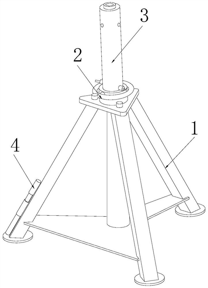
[0029] as attached figure 1 to attach Image 6 Shown:

[0030] The present invention provides a communication equipment bracket with a protective effect. The structure includes a bracket 1, an adjustment rod 2, a support rod 3, and a breaker 4. The bottom surface of the adjustment rod 2 is fixed on the top of the bracket 1, and the bottom of the support rod 3 Covered on the inner top of the adjusting rod 2, the right side of the breaker 4 is installed on the left slope near the bottom of the bracket 1.

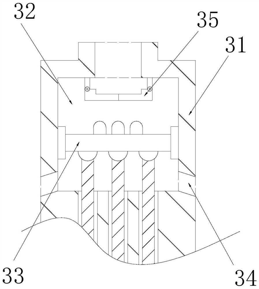
[0031] The support rod 3 includes a rod body 31, an inner cavity 32, a conductive plate 33, a drain port 34, and a collection mechanism 35. The inner cavity 32 is arranged on the inner top of the rod body 31, and the left and right ends of the conductive plate 33 are installed in the inner cavity 32. The left and right inner walls, the drainage port 34 runs through the left and right surfaces of the rod body 31 , and the inner end communicates with the inner bottom of the in...

Embodiment 2

[0039] as attached Figure 7 to attach Figure 9 Shown:

[0040] Wherein, the drain port 34 includes a sleeve 341, a swing plate 342, and a reset bar 343, the top of the swing plate 342 is hingedly connected to the inner top of the sleeve 341, and the bottom end of the reset bar 343 is installed on the top of the swing plate 342. On the right side, the reset bar 343 is provided with two, which can increase the driving force of the reset bar 343 to the swing plate 342, accelerate the reset speed of the swing plate 342, and pass through the swing plate 342 to the rainwater that passes along the outside of the drain port 34. block.

[0041] Wherein, the swing plate 342 includes a connection plate 42a, a push bar 42b, and a push plate 42c, the top of the push bar 42b is connected to the middle part of the bottom surface of the connection plate 42a, and the middle part of the upper surface of the push plate 42c is fixed on the bottom end of the push bar 42b , the push bar 42b is...


PUM


Abstract

The invention discloses a communication equipment support with a protection function. The support structurally comprises the support, an adjusting rod, a supporting rod and a circuit breaker. The bottom surface of the adjusting rod is fixed to the top of the support, and rainwater easily enters the supporting rod along an opening so that a current-conducting plate in the supporting rod is soaked in the rainwater for a long time; by arranging the collecting mechanism at the inner top of the inner cavity, rainwater can be blocked and collected, long-term soaking of the current-conducting plate in the rainwater can be reduced, gradual rust on the outer wall of the current-conducting plate is reduced, the service life of the current-conducting plate is prolonged, and normal contact and electrification of the current-conducting plate and the bottom of the antenna are facilitated; and the water outlet is smooth, in a rainy environment, the rainwater easily flows into the inner cavity along the water outlet, the swing plate is arranged in the water outlet, external rainwater is blocked through the swing plate, the external rainwater flowing into the inner cavity along the water outlet is reduced, and the situation that a large amount of rainwater is accumulated in the inner cavity can be decreased.

Description

technical field [0001] The invention belongs to the technical field of communication, and more specifically, relates to a communication equipment bracket with a protective function. Background technique [0002] The antenna is often used to receive the network signal and transmit the signal for use by other equipment. The antenna is a type of communication equipment. The antenna is supported by a bracket, and the bottom of the antenna is inserted into the top of the support rod. The end contact is energized, the antenna receives the signal, and the bracket is equipped with a breaker. When it is thunderstorm, the power of the antenna is cut off to protect the antenna; when the bracket is used to support the antenna in the prior art, because the top of the support rod is open , in a rainy environment, and when the antenna is not installed on the top of the support rod, rainwater will easily enter the inside of the support rod along the opening, causing the conductive plate ins...

Claims


Application Information

Patent Timeline
IPC IPC(8): H01Q1/12
CPCH01Q1/12
Inventor 周迪
Owner 周迪
Why Eureka
Try Eureka