Contact ring and contact system

A technology of contact system and contact ring, applied in the direction of contact parts, connection contact materials, connections, etc., can solve the problems of non-conductive connection, low efficiency of electromagnetic shielding, poor electrothermal performance, etc.

Pending Publication Date: 2021-11-02
TE CONNECTIVITY GERMANY GMBH
View PDF0 Cites 0 Cited by
  • Summary
  • Abstract
  • Description
  • Claims
  • Application Information

AI Technical Summary

Problems solved by technology

The contact ring 3 is flat and wavy, and is usually made of spring steel, which has good mechanical properties but poor electrothermal properties, which is also difficult to compensate with thick silver plating
The contact parts of known contact rings also do not reliably penetrate electrically insulating surface layers, such as aluminum oxide, with typical contact forces
they are also prone to corrosion
[0004] The contact element, although it contains a conductive material whose surface is made of an electrically insulating layer such as a natural oxide, cannot be connected in an adequately conductive manner by the contact elements described in the prior art
Furthermore, the contact elements are not configured to avoid air gaps between the contact elements
Therefore, the electromagnetic shielding of this connection is ineffective at high frequencies

Method used


Image

  • Contact ring and contact system
  • Contact ring and contact system
  • Contact ring and contact system

Examples


Embodiment Construction

[0053] The following will refer to Figures 2A to 13D Embodiments of the present invention are described in detail.

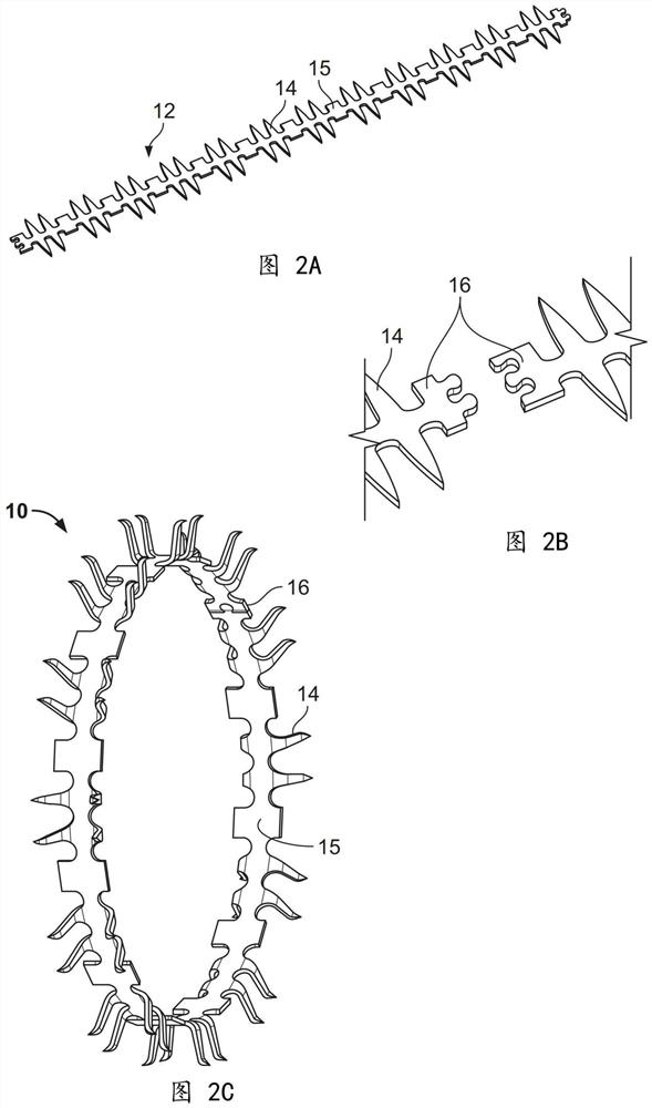
[0054] Figures 2A to 2C A contact ring 10 according to a first embodiment of the invention is shown. like Figure 2A As shown, the contact ring 10 comprises a strip 12 of electrically conductive material. The strip 12 is provided with protrusions 14 on at least one longitudinal side. The protrusion 14 tapers and forms a point at its end. Figure 2B It is shown that the strip 12 may be equipped with closures 16 at the ends, which allow the strip 12 to be closed to form an annular cylindrically arranged structure, as in Figure 2C can be seen in . This construction allows simple and inexpensive production of the contact ring 10 by punching and bending. like Figure 2C As shown, the protrusions 14 are curved outwards and have an S-shaped cross-section.

[0055] A helical spring (not shown) may optionally surround the contact ring 10 concentrically, makin...


PUM


Abstract

The present invention relates to a contact ring (10, 100) for connecting at least a first and a second electrically conductive contact element (1, 2), the contact ring (10, 100, 1000) comprising: a strip (12) comprising electrically conductive material, wherein the strip (12) comprises a plurality of projections (14, 104, 1004) on at least one longitudinal side, wherein the projections (14, 104) are configured such that they contact the electrically conductive materials of the contact elements (1, 2) and establish an electrically conductive connection therebetween. The present invention further relates to a contact system composed of a contact ring (100), a ground cylinder (200), and a shielding cylinder (300) with centering projections, where the contact ring is disposed between the two cylinders and where the ground cylinder (200) and the shielding cylinder (300) are connected to one another by a press-fit.

Description

technical field [0001] The invention relates to a contact ring which electrically connects contact elements and to a contact system comprising a grounded cylinder, a shielding cylinder and a contact ring which electrically connects the two cylinders. Background technique [0002] Known contact rings are in the form of compression spring contacts, which are made of electrically conductive material and can thus establish an electrically conductive connection between the contact elements. These contact rings are generally flat and have, for example, a wave shape, so that they alternately touch the surface of the contact element. [0003] Figure 1A and 1B Two contact elements 1 and 2 are shown without connecting members ( Figure 1A ) and two contact elements 3 with connecting member 3 ( Figure 1B ) of the regular arrangement. Figure 1B The connection member 3 in is a typical contact ring 3 known from the prior art. The contact ring 3 is flat and wavy, and is usually made...

Claims


Application Information

Patent Timeline
Patent Type & Authority Applications(China)
IPC IPC(8): H01R13/24H01R4/58
CPCH01R13/2421H01R13/2464H01R4/58H01R13/15H01R13/6583H01R4/26
Inventor I.伊万诺夫M.伯格哈特H.施密特H.波洛克S.萨克斯M.沃尔夫C.科斯马尔斯基M.利斯廷U.布尔杜克J.费蒂格W.迪特里希
Owner TE CONNECTIVITY GERMANY GMBH
Why Eureka
Try Eureka