
A pipeline alignment method

A pipeline and centering device technology, applied to tubular objects, auxiliary welding equipment, welding equipment, etc., can solve problems such as poor centrality control, affecting the quality and volume of pipeline installation in tunnels, and achieve convenient pipeline centering Effect

Active Publication Date: 2019-07-12
BEIHUA UNIV
View PDF3 Cites 0 Cited by
  • Summary
  • Abstract
  • Description
  • Claims
  • Application Information

AI Technical Summary

Problems solved by technology

[0002] In the prior art, when carrying out on-site construction of long-distance oil and gas pipelines, butt welding between two pipelines is a necessary construction procedure. At present, the main lifting equipment used in the alignment of steel pipes is pipelayers and excavators. Or cranes, use these equipment to lift the pipeline, and then carry out the matching and welding. Due to the large size of these equipment, they can only be carried out in an environment with a large space. When the pipeline construction enters the tunnel, the construction space is relatively small. Therefore, when carrying out the butt welding of the pipeline in the tunnel, a special mobile pipe hanger will be used to lift the steel pipe, and then the butt joint and welding of the pipeline will be carried out. The shortcoming of the prior art is: in the actual situation on site, especially in the tunnel During the construction of pipeline pairing, large equipment such as pipelayers cannot participate in the lifting construction. The mobile pipelayer truck used to lift steel pipes is difficult to control the centrality of the steel pipe pairing. Deviation from the actual required installation line will affect the quality of pipeline installation in the tunnel

Method used


Image

  • A pipeline alignment method
  • A pipeline alignment method
  • A pipeline alignment method

Examples


Embodiment Construction

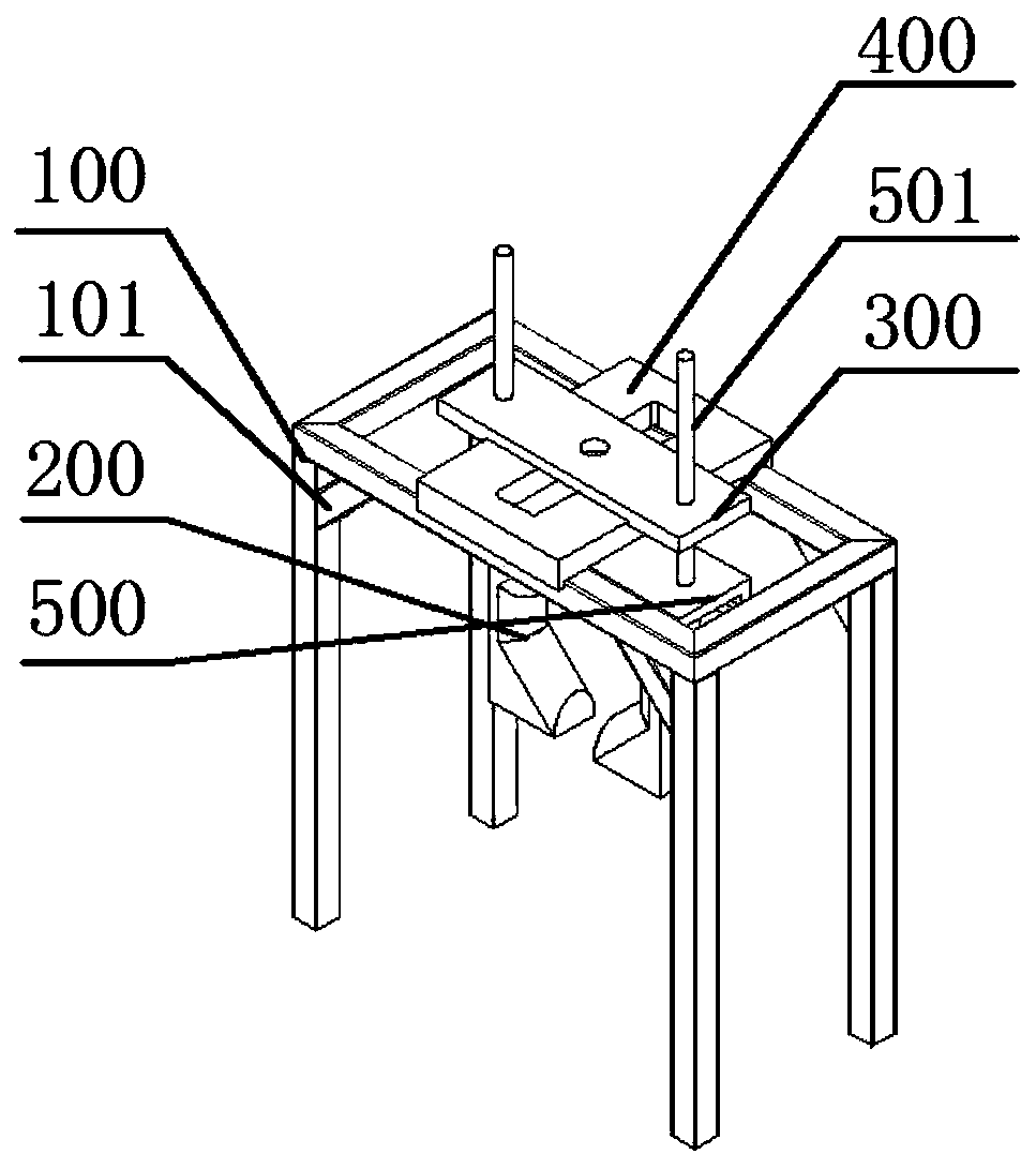
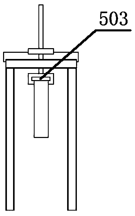
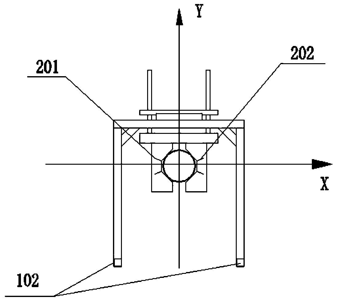
[0022] Such as figure 1 A pipeline centering device shown includes a bracket 100, a Z-axis moving table 300, a Y-axis moving table 500, an X-axis moving table 400, and a clamping mechanism 200. The clamping mechanism 200 includes a first clamp 201 and a second clamp 202, the Y-axis mobile platform 500 includes a lower slideway 503 and an upper guide column 501, the first clamp 201 and the second clamp 202 are connected to the Y-axis mobile platform 500 through the slideway 503, and the X-axis mobile platform 400 is placed on the bracket On the upper end of 100, the Z-axis mobile platform 300 is placed above the X-axis mobile platform 400, and the guide column 501 passes through the X-axis mobile platform 400, and can slide up and down within the length of the guide column 501, such as image 3 The shown first clamp 201 and the second clamp 202 have the same structure, and are vertically placed in a "concave" shape, and the concave openings are opposite to each other for placin...


PUM


Abstract

The invention discloses a pipeline centring method. The pipeline centring method comprises the steps that centring devices are jointed; initial values are set; the coordinates on a first pipeline aredetermined; the axis equation of the first pipeline is determined; the coordinates on a second pipeline are guided out; displacement is determined; and centring is carried out according to the displacement. Meanwhile, the centring devices with clamping mechanisms are adopted. The centring method is provided, the centring devices which are provided with the clamping mechanisms and can move in the Xdirection, the Y direction and the Z direction are adopted, the coordinates of the first pipeline are adopted as the datum, the second pipeline is adjusted through the displacement, and therefore fast, effective and convenient pipeline centring is achieved.

Description

technical field [0001] The invention relates to pipeline installation technology, in particular to a pipeline centering method. Background technique [0002] In the prior art, when carrying out on-site construction of long-distance oil and gas pipelines, butt welding between two pipelines is a necessary construction procedure. At present, the main lifting equipment used in the alignment of steel pipes is pipelayers and excavators. Or cranes, use these equipment to lift the pipeline, and then carry out the matching and welding. Due to the large size of these equipment, they can only be carried out in an environment with a large space. When the pipeline construction enters the tunnel, the construction space is relatively small. Therefore, when carrying out the butt welding of the pipeline in the tunnel, a special mobile pipe hanger will be used to lift the steel pipe, and then the butt joint and welding of the pipeline will be carried out. The shortcoming of the prior art is: ...

Claims


Application Information

Patent Timeline
Patent Type & Authority Patents(China)
IPC IPC(8): B23K37/053B23K101/06
CPCB23K37/0533
Inventor 张玉峰裴杰牛莉莉王月刘通孙永强毕帅男张卫军周睿杰
Owner BEIHUA UNIV
Learn More