

Auxiliary nursing facility for bedridden patient in neurology department nursing
A technology for neurology and patients, applied in hospital beds, medical science, hospital equipment, etc., can solve problems such as troublesome incontinence management, and achieve the effects of complete functions, reduced pollution, and low production costs
- Summary
- Abstract
- Description
- Claims
- Application Information
AI Technical Summary
Problems solved by technology
Method used
Image

Examples
Embodiment Construction
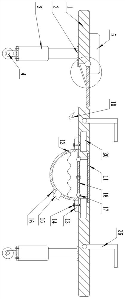
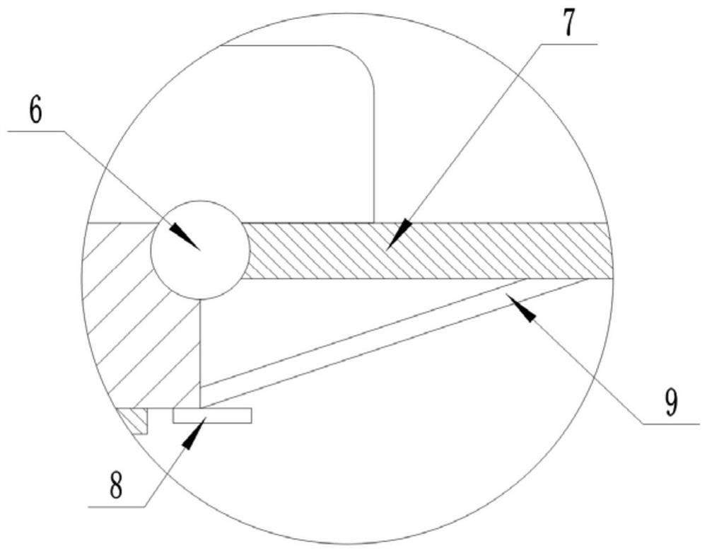
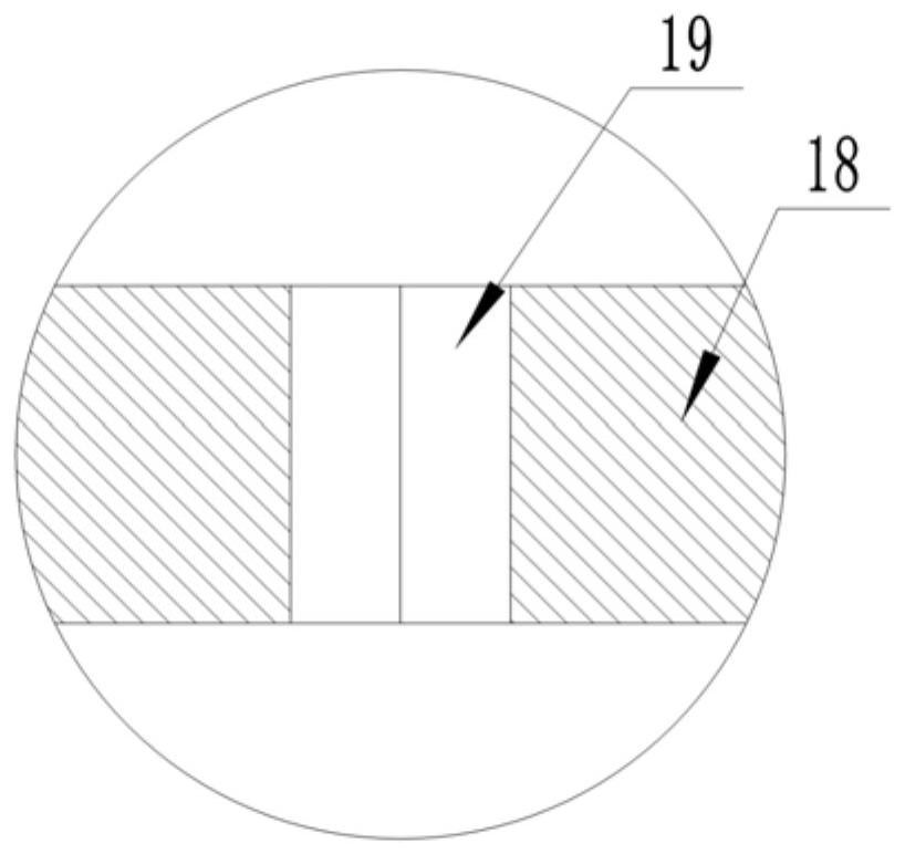
[0024] Such as Figure 1 to Figure 7 As shown, this specific embodiment adopts the following technical solutions: a kind of auxiliary nursing facility for bedridden patients in the Department of Neurology, comprising a bed body 1, a mounting plate-2, a supporting foot 3, a universal wheel 4, a pillow 5, and a rotating shaft-6 , Cover plate 7, Limiting plate 8, Support rod 9, Hook 10, Connecting plate 11, Collection box 12, Fixed block 1 13, Bolt 14, Waste port 15, Control valve 16, Rotating shaft 2 17, Baffle plate 18, Washer 19. Limb fixing device 20 and limb holding device 36; the lower surface of the bed body 1 is fixedly connected with a mounting plate 2 around, and the bottom end of the mounting plate 2 is fixedly connected with a supporting foot 3, and the bottom of the supporting foot 3 The end is fixedly connected with a universal wheel 4; the left side of the upper end of the bed 1 is connected with a pillow 5; the left side of the upper end of the bed 1 is provided w...
PUM
| Property | Measurement | Unit |
|---|---|---|
| Rotation angle | aaaaa | aaaaa |
Abstract
Description
Claims
Application Information