A smart bicycle solar tail light
A technology for solar taillights and smart bicycles, applied in bicycle accessories, optical signals, transportation and packaging, etc., can solve the problems of easy collision, low safety, and difficult to identify taillights, so as to achieve easy identification, reduce accidents, and improve safety. Effects of Sex and Usage
- Summary
- Abstract
- Description
- Claims
- Application Information
AI Technical Summary
Problems solved by technology
Method used
Image


Examples
Embodiment 1
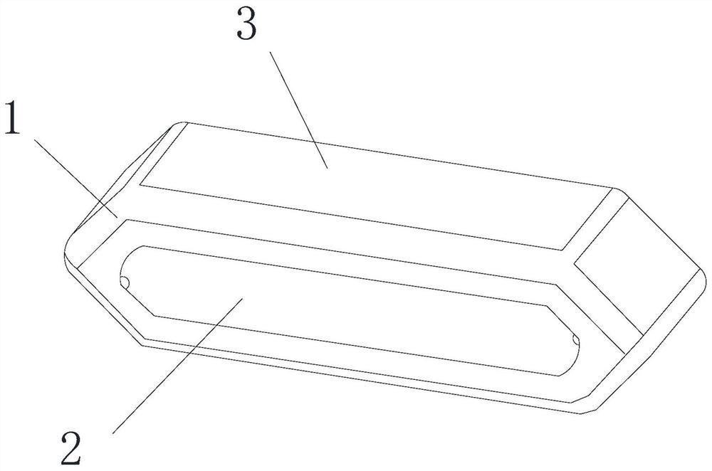
[0055] The embodiment of the present invention provides a smart bicycle solar tail light, such as Figure 1-Figure 12 As shown, it includes: a taillight body, the taillight body includes a housing 1, a display screen 2 is arranged on the front of the housing 1, a solar panel 3 is arranged on the top surface of the housing 1, a circuit control board 4 is arranged inside the housing 1, and the An LED light group 5 is arranged on the front of the circuit control board 4 , and the circuit control board 4 can control the LED light group 5 to change the display state according to the running state of the bicycle.
[0056] The working principle and beneficial effects of the above technical solutions are as follows: the smart bicycle solar taillight of the present invention includes a taillight body, the exterior of the taillight body is an outer shell 1, and a solar panel 3 is arranged on the top surface of the outer shell 1, and the taillight body can be charged by solar energy. A d...
Embodiment 2
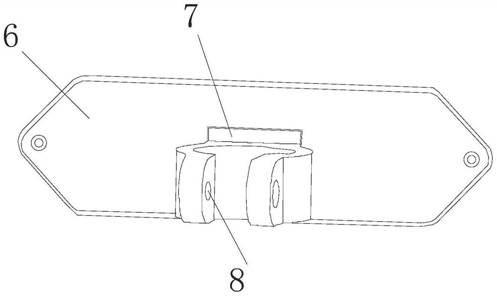
[0058] On the basis of the above Example 1, as figure 1 , figure 2 As shown, a back cover 6 is provided on the back of the housing 1, and the back cover 6 is detachably connected to the back of the housing 1;
[0059] A fixing seat 7 is provided on the side of the rear cover 6 away from the casing 1 , and fixing holes 8 are provided on the left and right sides of the fixing seat 7 .
[0060] The working principle and beneficial effects of the above technical solutions are as follows: a rear cover 6 is arranged on the back of the casing 1, and the rear cover 6 is detachably connected to the back of the casing 1, and the rear cover 6 can be installed on the back of the casing 1 by means of bolt installation, and the back of the rear cover 6 A fixing seat 7 is provided, and a fixing hole 8 is arranged on the fixing seat 7, and the rear cover 6 can be installed under the bicycle saddle through the fixing seat 7, and the installation of the tail light body is realized.
Embodiment 3
[0062] On the basis of Example 1, as Figure 3-Figure 5 As shown, a charging port 9, a first opening 10 and a second opening 70 are opened at the bottom of the casing 1 in sequence from left to right;
[0063] The front side wall of the circuit control board 4 is provided with a gyroscope 11 , a charging interface 12 , a button 13 and a switch 14 , and the circuit control board 4 is respectively connected with the switch 14 , the button 13 , the gyroscope 11 and the The LED light group 5 is electrically connected;
[0064] The casing 1 is also provided with a battery and a charging circuit, the battery is electrically connected to the switch 14 and the charging circuit respectively, the charging interface 12 is electrically connected to the charging circuit, and the solar panel 3 electrically connected to the charging circuit;
[0065] The charging port 12 extends through the charging port 9 to the outside of the casing 1 , the button 13 extends through the first opening 10 ...
PUM
 Abstract
Description
Claims
Application Information
 - R&D
- Intellectual Property
- Life Sciences
- Materials
- Tech Scout
- Unparalleled Data Quality
- Higher Quality Content
- 60% Fewer Hallucinations
Browse by: Latest US Patents, China's latest patents, Technical Efficacy Thesaurus, Application Domain, Technology Topic, Popular Technical Reports.
© 2025 PatSnap. All rights reserved.Legal|Privacy policy|Modern Slavery Act Transparency Statement|Sitemap|About US| Contact US: help@patsnap.com