Resistance mechanism and chest expander

A tensioner and resistance technology, which is applied to gymnastics equipment, muscle training equipment, sports accessories, etc., can solve the problem that the resistance of the tensioner cannot be adjusted, and achieve the effect of wide application and convenient use.

Pending Publication Date: 2021-11-09
湖南依讯诺科技有限公司
View PDF0 Cites 3 Cited by
  • Summary
  • Abstract
  • Description
  • Claims
  • Application Information

AI Technical Summary

Problems solved by technology

[0007] The object of the present invention is to provide a resistance mechanism and a tensioner to solve the technical problem in the prior art that the resistance of the tensioner cannot be adjusted when the user uses the tensioner; The many technical effects that can be produced are detailed in the following

Method used


Image

  • Resistance mechanism and chest expander
  • Resistance mechanism and chest expander
  • Resistance mechanism and chest expander

Examples


Embodiment 1

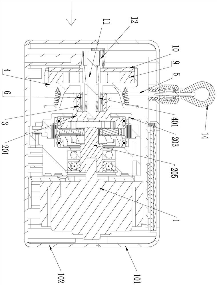
[0044] like Figure 1-Figure 7 As shown, this embodiment provides a resistance mechanism, which is arranged in the tensioner and includes a clutch part, a deceleration device 2 and a hysteresis brake 1, wherein: the output shaft of the hysteresis brake 1 is in drive connection with the input shaft of the deceleration device 2, Changing the current input to the hysteresis brake 1 can adjust the output torque of the deceleration device 2; the clutch part is located between the deceleration device 2 and the reel 4, and when the tension rope 5 is pulled out and drives the reel 4 to rotate forward, the clutch part will The deceleration device 2 and the reel 4 are connected in transmission, and when the tension rope 5 is recovered and drives the reel 4 to reverse, the clutch part makes the deceleration device 2 and the reel 4 disengage. A tension rope 5 is wound on the above-mentioned reel 4 .

[0045] Wherein, the above-mentioned "forward" and "reverse" refer to relative terms, if...

Embodiment 2

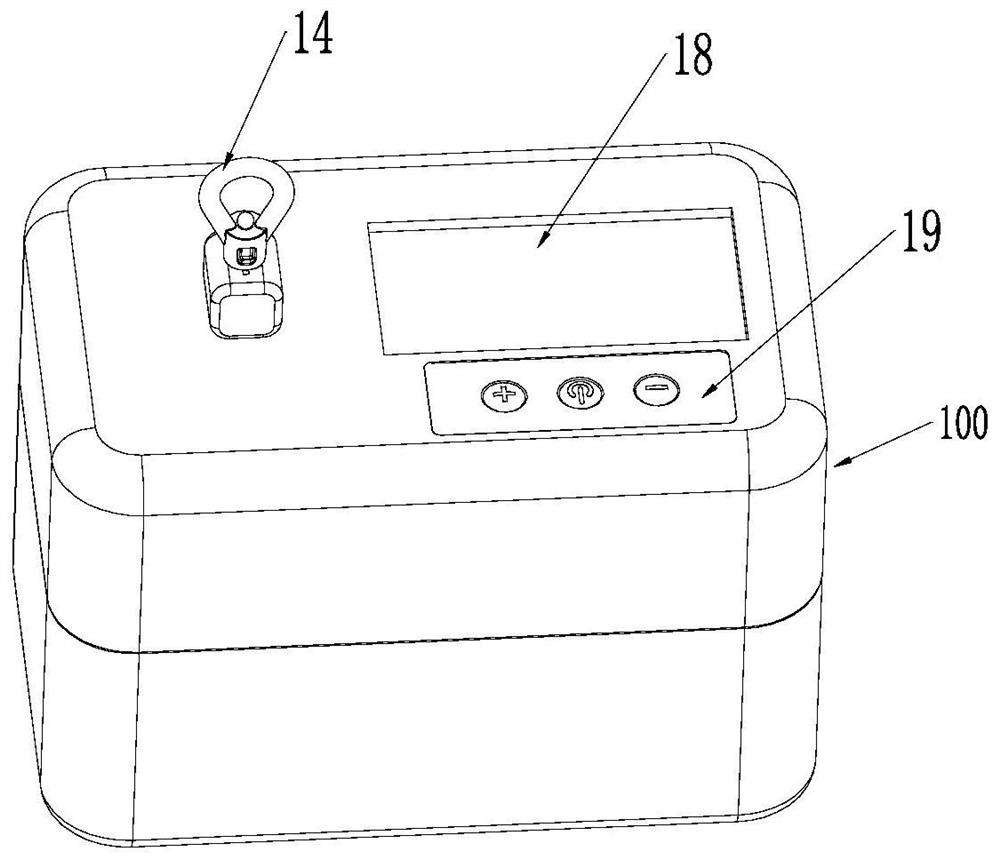
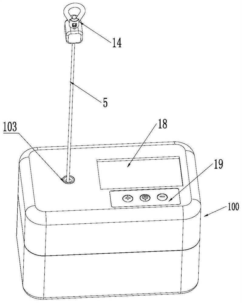
[0070] This embodiment provides a tensioner, see Figure 1-Figure 3 , Figure 4 As shown, the tensioner includes a casing 100 , the above-mentioned resistance mechanism and a winding wheel 4 located in the casing 100 , the winding wheel 4 is rotatably connected to the casing 100 , and a tension rope 5 is wound on the winding wheel 4 . Wherein, the casing is detachably connected by an upper casing 101 and a bottom casing 102 for easy installation and disassembly; the hysteresis brake 1 is installed in the casing 100 through a fixing frame 17 .

[0071] The tension device with the above-mentioned resistance mechanism can adjust the resistance according to the specific needs of the user, and is easy to use and has a wide application range.

[0072] After the user loosens the tension rope 5, in order to facilitate the automatic recovery of the tension rope 5, the tensioner also includes elastic parts, which are used to pull the reel 4 to reset after elastic deformation, so as to ...


PUM


Abstract

The invention provides a resistance mechanism and a chest expander, relates to the technical field of fitness equipment, and solves the technical problem that the resistance of a chest expander cannot be adjusted. The resistance mechanism comprises a clutch component, a speed reducer and a hysteresis brake, an output shaft of the hysteresis brake is in transmission connection with an input shaft of the speed reducer, and the output torque of the speed reducer can be adjusted by changing the current input into the hysteresis brake; the clutch component is located between the speed reducer and a winding wheel, when a pull rope is pulled out and drives the winding wheel to rotate forwards, the clutch component enables the speed reducer and the winding wheel to be in transmission connection, and when the pull rope is retracted and drives the winding wheel to rotate reversely, the clutch component enables the speed reducer and the winding wheel to be separated. The output torque of the hysteresis brake can be adjusted by changing the magnitude of the current input to the hysteresis brake, that is, the resistance mechanism can form different magnitudes of resistance for preventing the winding wheel from rotating; and the resistance can be adjusted in a stepless mode, and use is more convenient.

Description

technical field [0001] The invention relates to the technical field of fitness equipment, in particular to a resistance mechanism and a tensioner. Background technique [0002] The tensioner is a device suitable for mass fitness exercises. Now people often use the fitness rope tensioner to shape the body and keep fit. [0003] Exercising rope tensioners in the prior art generally include a housing and a tension rope wrapped in the housing. When a user uses the tensioner, the user overcomes the resistance of the tension rope and pulls it, thereby achieving the effect of exercise. [0004] The applicant finds that the prior art has at least the following technical problems: [0005] In an existing tension device, the tension rope is made of elastic material. The longer the rope is stretched, the greater the tension will be. The strength of the tension cannot be constant, and it is difficult to detect the magnitude of the tension. The magnitude of the pulling force and the c...

Claims


Application Information

Patent Timeline
Patent Type & Authority Applications(China)
IPC IPC(8): A63B21/005
CPCA63B21/0054A63B21/005
Inventor 余源泉
Owner 湖南依讯诺科技有限公司
Why Eureka
Try Eureka