
Pipe gallery construction formwork jumbo control system

A formwork trolley and control system technology, applied in the field of hydraulic control, can solve problems such as affecting construction efficiency, affecting formwork efficiency, low transmission efficiency, etc., to achieve improved efficiency and accuracy, guarantee formwork efficiency, and a high degree of automation. Effect

Inactive Publication Date: 2018-11-23
CHINA 19TH METALLURGICAL CORP
View PDF3 Cites 0 Cited by
  • Summary
  • Abstract
  • Description
  • Claims
  • Application Information

AI Technical Summary

Problems solved by technology

There are many transmission parts, which reduces the transmission reliability. At the same time, the transmission efficiency of the worm gear reducer is also relatively low. Especially when the left and right driving wheels are not synchronized, the chain on the side with the larger driving force is prone to breakage. Affect construction efficiency
For the hydraulically driven walking mechanism, the hydraulic cylinder is usually used to drive the formwork trolley to walk, but there are still problems such as complex transmission parts, low transmission efficiency, and slow walking speed, which affect the efficiency of formwork support
[0004] The formwork support system of the formwork trolley usually uses a screw screw mechanism or a screw jack to realize the formwork support and demolition action of the formwork. The operation of the screw jack cannot be controlled centrally, and more labor is required; at the same time, during the operation of the screw jack, During the operation, the operator needs to stand under the beam of the frame of the trolley, which has certain potential safety hazards
The screw jack or lead screw mechanism cannot achieve precise synchronization, and the formwork is prone to deflection during the movement process, which affects the efficiency of the formwork

Method used


Image

  • Pipe gallery construction formwork jumbo control system

Examples


Embodiment Construction

[0026] Below in conjunction with accompanying drawing and embodiment the present invention is described further as follows:

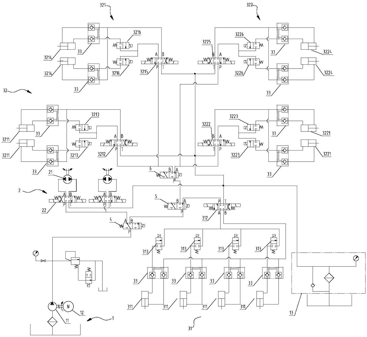
[0027] Such as figure 1 As shown, the control system of the formwork trolley for pipe gallery construction includes oil supply system 1, travel system 2, formwork support system 3 and two-position three-way valve A4;

[0028] The oil supply system 1 includes an oil pump 11 and an electric motor 12 arranged on the main oil inlet pipeline, and the electric motor 12 drives the oil pump 11 to provide hydraulic oil required by the entire control system;

[0029] The walking system 2 includes a hydraulic motor 21 and a motor reversing valve 22; the working port of the motor reversing valve 22 communicates with the corresponding oil port of the hydraulic motor 21;

[0030] One of the oil outlets of the two-position three-way valve A4 is connected to the oil inlet of the motor reversing valve 22 through the corresponding oil inlet pipeline, and the other oil o...


PUM


Abstract

The invention belongs to the field of hydraulic control, relates to a pipe gallery construction formwork jumbo control system, and is intended to provide higher automation level and higher formwork erection efficiency. The pipe gallery construction formwork jumbo control system comprises an oil supply system, a traveling system and a formwork support system and two-position three-way valve A; theoil supply system drives an oil pump through a motor to provide hydraulic oil that the whole control system requires; the traveling system comprises a hydraulic motor and a motor reversing valve connected with the same; one oil outlet of the two-position three-way valve A is connected with an oil inlet of the motor reversing valve, the other oil outlet of the two-position three-way valve A is connected with an oil incoming line of the formwork support system; an oil inlet of the two-position three-way valve A is connected with a main oil line. The traveling system and the formwork support system share one oil supply system, providing good convenience of operation and high automation level. A formwork jumbo is driven to move through the hydraulic motor, the transmission path is short, and transmission efficiency is high. The two-position three-way valve A allows interlocking of the traveling system and the formwork jumbo damage, formwork support error and the like; formwork erection efficiency is ensured.

Description

technical field [0001] The invention belongs to the technical field of hydraulic control, in particular to a control system for a formwork trolley for pipe gallery construction. Background technique [0002] The underground comprehensive pipe gallery refers to the public tunnel used for centralized laying of electric power, communication, radio and television, water supply, drainage, heat, gas and other municipal pipelines underground in the city. At present, the construction of smart pipe gallery has become the general trend, and the use of formwork trolleys for pipe gallery pouring has attracted much attention because it avoids the various disadvantages of traditional scaffolding formwork. The existing formwork trolley mainly includes a traveling mechanism and a formwork supporting system. The traveling mechanism drives the formwork trolley to move according to requirements, and the formwork supporting system realizes actions such as formwork support and formwork removal. ...

Claims


Application Information

Patent Timeline
IPC IPC(8): E02D29/045
CPCE02D29/045E02D29/10
Inventor 孟晓宏胡伟山谷昌满
Owner CHINA 19TH METALLURGICAL CORP
Learn More