
Anti-freezing pneumatic pick

A technology of air picks and pick barrels, which is applied in the direction of picks, striking tools, light impact tools, etc. It can solve the problems that are difficult to apply, affect the high-pressure air source to quickly enter the pick barrel, and condense, so as to achieve the effect of good antifreeze function

Pending Publication Date: 2021-11-09
唐金浩
View PDF0 Cites 0 Cited by
  • Summary
  • Abstract
  • Description
  • Claims
  • Application Information

AI Technical Summary

Problems solved by technology

At present, the high-pressure air source directly enters the pick barrel through the small hole on the valve cabinet, and the high-pressure air source will contain a certain amount of water. When the air pick is used in a cold climate area, the water contained in the high-pressure air source will When passing through the above-mentioned small holes, condensation often occurs, which will affect the rapid entry of high-pressure air into the pick barrel
If it is necessary to simply increase the diameter of the small hole to form a large hole in order to prevent freezing, it is easy to cause the hammer body to be unable to push the hammer body to impact the pick brazing due to insufficient air pressure in the pick cylinder. That is to say, the existing air picks do not have the antifreeze function, so it is difficult to It is suitable for use in cold weather or alpine regions, which brings certain restrictions to the range of use

Method used


Image

  • Anti-freezing pneumatic pick
  • Anti-freezing pneumatic pick
  • Anti-freezing pneumatic pick

Examples


Embodiment Construction

[0023] The embodiments of the present invention will be described in detail below according to the above-mentioned drawings.

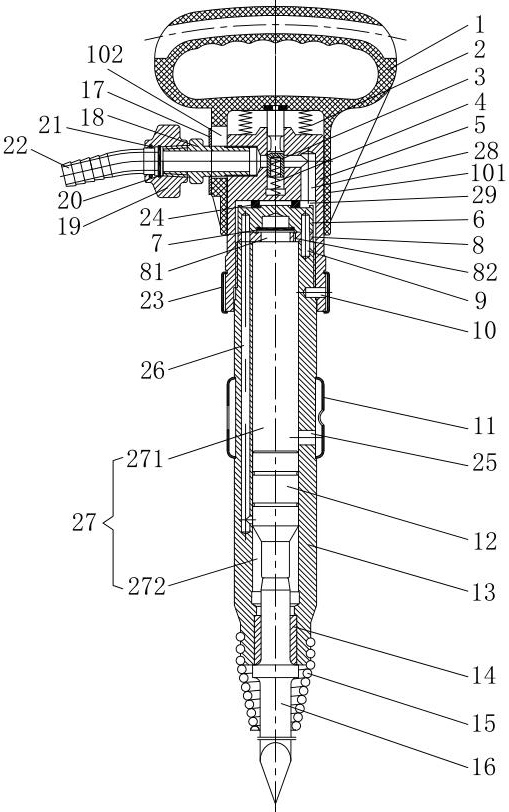
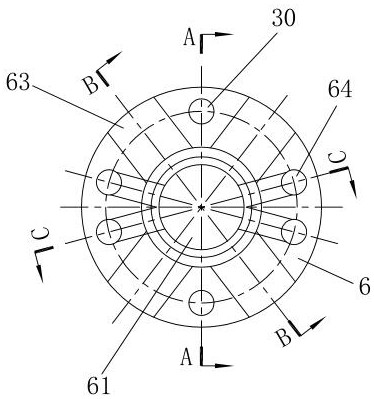
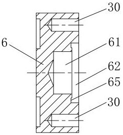
[0024] Such as Figure 1~Figure 7 As shown, 1. pick handle, 101. handle cover, 102. movable hole, 2. pick handle spring, 3. blocking valve, 4. blocking valve spring, 5. handle body, 6. valve cabinet, 61. valve cabinet hole , 62. Valve plate hole, 63. Ventilation groove, 64. Valve cabinet connection hole, 65. Ring groove, 7. Valve plate, 8. Valve pad, 81. Valve pad hole, 82. Return air hole, 83. Valve Pad connection hole, 9. Locating pin, 10. Stop pin, 11. Windshield, 12. Hammer body, 13. Pick barrel, 14. Brazing sleeve, 15. Head spring, 16. Pick brazing, 17. Washer, 18. Connecting pipe, 19. Nut, 20. Retaining ring for hole, 21. O-ring, 22. Air pipe, 23. Circlip, 24. Retaining ring, 25. Exhaust hole, 26. Air intake hole, 27. Working chamber, 271. Upper chamber, 272. Lower chamber, 28. Air intake channel, 29. Air intake chamber, 30. Pin hole.

[0025]...


PUM


Abstract

The invention discloses an anti-freezing pneumatic pick which comprises a handle body, a pick handle, a valve cabinet, a valve pad, a pick barrel, a pick-rod assembly and the like. A valve cabinet hole is formed in the valve cabinet and can communicate with a lower cavity in the pick barrel through an air inlet hole, a valve pad hole is formed in the valve pad and can communicate with an upper cavity in the pick barrel, a valve plate hole and a valve plate which communicate with an air inlet cavity are additionally arranged between the valve cabinet hole and the valve pad hole; and in the way, the valve pad hole is closed and the valve cabinet hole is opened or the valve pad hole is opened and the valve cabinet hole is closed through lifting of the valve plate in the valve plate hole, and therefore energy storage and acting of a hammer body on the pick-rod assembly are achieved. Therefore, a high-pressure air source enters the pick barrel through the valve cabinet hole, the valve pad hole and the valve plate hole, the access hole diameter can be increased, the valve plate is designed to prevent insufficient air pressure in the pick barrel, and on the basis that it is guaranteed that the hammer body can still be forcefully pushed in the pick barrel to impact the pick-rod assembly to achieve crushing use, the better anti-freezing function is achieved; and therefore, the anti-freezing pneumatic pick is better suitable for cold and alpine regions, and the application range is not limited by climate.

Description

technical field [0001] The invention relates to an air pick used for breaking concrete, road surfaces and other hard objects, in particular to an antifreeze air pick. Background technique [0002] The air pick is a kind of high-pressure air source that is connected as the driving force to enter the pick barrel, and then push the hammer body in the pick barrel to move up and down to reciprocate the pick drill at the bottom of the pick barrel, and then the hammer drill after impact breaks concrete and road surface Pneumatic tools for pneumatic tools and other hard objects are often used in civil engineering, highways, subways and other constructions to destroy various solid objects, and can also be used for drilling, perforating, and trenching in frozen ground. At present, the high-pressure air source directly enters the pick barrel through the small hole on the valve cabinet, and the high-pressure air source will contain a certain amount of water. When the air pick is used in...

Claims


Application Information

Patent Timeline
Patent Type & Authority Applications(China)
IPC IPC(8): B25D9/00B25D7/00
CPCB25D9/00B25D7/00
Inventor 唐金浩
Owner 唐金浩
Learn More