Pressure generation deceleration strip device based on gas-liquid coupling

A technology of pressure power generation and gas-liquid coupling, which is applied in the direction of engine components, machines/engines, mechanisms that generate mechanical power, etc., can solve the problem of spring or spring gasket losing elasticity, increasing spring cost and maintenance cost, and shortening the service life of generators and other problems, to achieve the effect of scientific structure principle, low manufacturing cost and ingenious design

Inactive Publication Date: 2018-10-23
NORTH CHINA UNIV OF WATER RESOURCES & ELECTRIC POWER
View PDF5 Cites 0 Cited by
  • Summary
  • Abstract
  • Description
  • Claims
  • Application Information

AI Technical Summary

Problems solved by technology

[0007] According to the survey, there are certain shortcomings in the previous research on the power generation of speed bumps: (1) Using springs or spring pads to make the speed bumps undulate, it is easy to make the springs or spring pads undulate in a short time on roads with large traffic volumes. The sheet loses its elasticity, which increases the spring cost and maintenance cost; (2) The generator rotates in both directions, which shortens the service life of the generator; (3) There is a lack of certain waterproof measures

Method used


Image

  • Pressure generation deceleration strip device based on gas-liquid coupling
  • Pressure generation deceleration strip device based on gas-liquid coupling
  • Pressure generation deceleration strip device based on gas-liquid coupling

Examples


Embodiment Construction

[0024] The present invention will be further described below in conjunction with the accompanying drawings and specific embodiments.

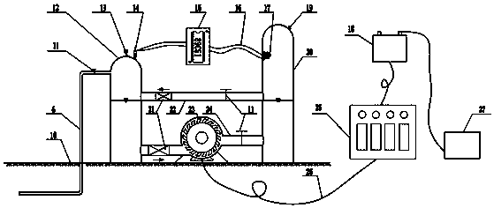
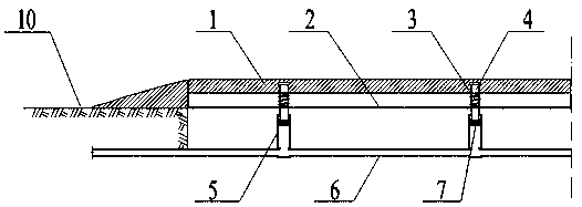
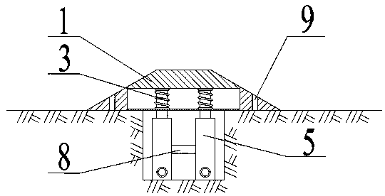
[0025] Such as figure 1 As shown, the present invention provides a pressure-generating deceleration belt device based on gas-liquid coupling, including a deceleration belt 1, a pneumatic transmission device arranged at the lower part of the deceleration belt 1, and a hydraulic transmission device arranged at one or both ends of the deceleration belt, The exhaust device and the electric device are automatically controlled. The pneumatic transmission device includes a pneumatic cylinder arranged under the speed reduction belt 1 and an air guide pipe 6 connected to the bottom of the pneumatic cylinder; the hydraulic power generation device includes a pressure tank 12, a turbine generator 23 and a water storage tank. 20. The air duct 6 communicates with the upper part of the pressure tank 12, and the lower part of the pressure tank 12 and the water...


PUM


Abstract

The invention provides a pressure generation deceleration strip device based on gas-liquid coupling. The pressure generation deceleration strip device comprises a deceleration strip and further comprises an air pressure transmission device arranged on the lower portion of the deceleration strip, a hydraulic transmission device, an automatic control exhaust device and an electric power device, wherein the hydraulic transmission device, the automatic control exhaust device and the electric power device are arranged at one or two ends of the deceleration strip. The air pressure transmission device comprises an air pressure cylinder arranged below the deceleration strip and an air guiding pipe communicating with the bottom of the air pressure cylinder. The hydraulic generation device comprisesa pressure tank, a generator and a water storage tank. The automatic control exhaust device comprises an electromagnetic automatic exhaust valve arranged on the upper portion of the pressure tank, aliquid level sensor arranged on the upper portion of the water storage tank and an automatic exhaust valve arranged at the top of the water storage tank, and a single chip microcomputer is arranged between the electromagnetic automatic exhaust valve and the liquid level sensor. The electric power device comprises a transformer connected with the generator and a storage battery connected with the transformer, and the storage battery is connected with electrical equipment.

Description

technical field [0001] The invention belongs to the field of power generation devices, and in particular relates to a pressure power generation speed bump device based on gas-liquid coupling. Background technique [0002] In the long history of human development and utilization of energy, the period of fossil energy such as oil, natural gas, and coal is only a short period of time. It is a historical necessity to replace fossil energy with new energy. How to develop new energy has become a common concern in today's society. Gravitational potential energy is one of the green energy sources, but due to its limitations, the current utilization rate is not high, and the technology of converting gravitational potential energy into electrical energy is even rarer. [0003] Speed ​​bumps are generally used to decelerate vehicles. The bumps it brings make passengers feel uncomfortable, but they can generate gravitational potential energy. Combined with the fact that China's road t...

Claims


Application Information

Patent Timeline
Patent Type & Authority Applications(China)
IPC IPC(8): E01F9/529F03G7/00F03B13/00
Inventor 张晓雷马洪福易明明徐志恒叶漪琦倪子涵汪世卓
Owner NORTH CHINA UNIV OF WATER RESOURCES & ELECTRIC POWER
Why Eureka
Try Eureka