
Protective grid mounting device for road construction

A technology for road construction and installation of devices, which is applied in the direction of roads, roads, road repairs, etc. It can solve the problems of protective grid tilting, edge fragmentation, and protective grid skew extrusion, etc., to prevent edge fragmentation and increase stability sexual effect

Inactive Publication Date: 2021-11-09
张彬
View PDF0 Cites 0 Cited by
  • Summary
  • Abstract
  • Description
  • Claims
  • Application Information

AI Technical Summary

Problems solved by technology

[0004] In order to overcome the existing device when installing this type of protective grid, because the reserved interval is only two centimeters, the position of the first protective grid is slightly deviated, which will cause the second protective grid to be difficult to install. In addition, the two When the protective grids are installed together, the protective grids will be tilted during the clamping process. At the same time, the two protective grids will be skewed and squeezed during transportation, and the edges will be broken. At the same time, during the installation process, the bottom of the protective grids It cannot be aligned with the preset groove at one time. In addition, when the existing device aligns the steel bars on the reserved vertical beams, the root of the steel bars will squeeze the reserved vertical beams, resulting in cement breakage at the connection between the steel bars and the reserved vertical beams phenomenon, the technical problem of the present invention is to provide a protective grid installation device for road construction

Method used


Image

  • Protective grid mounting device for road construction
  • Protective grid mounting device for road construction
  • Protective grid mounting device for road construction

Examples


Embodiment

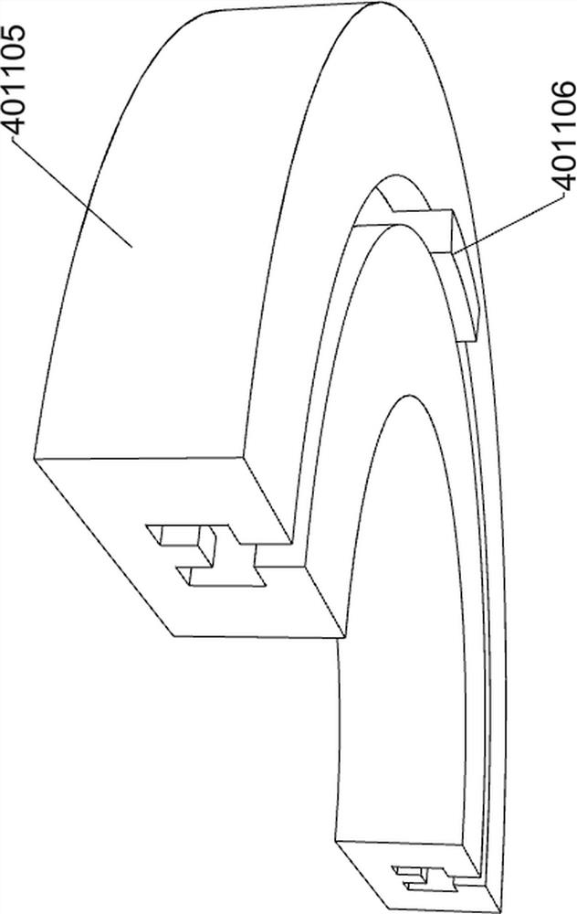
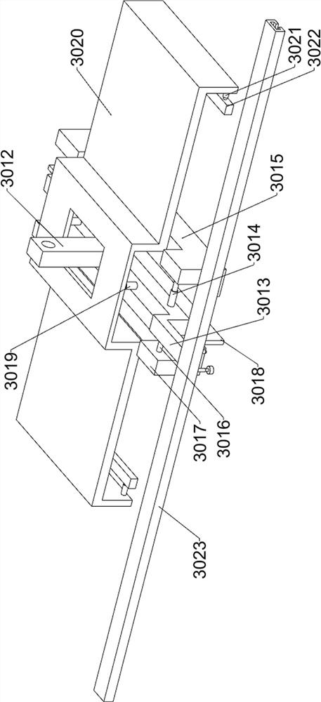
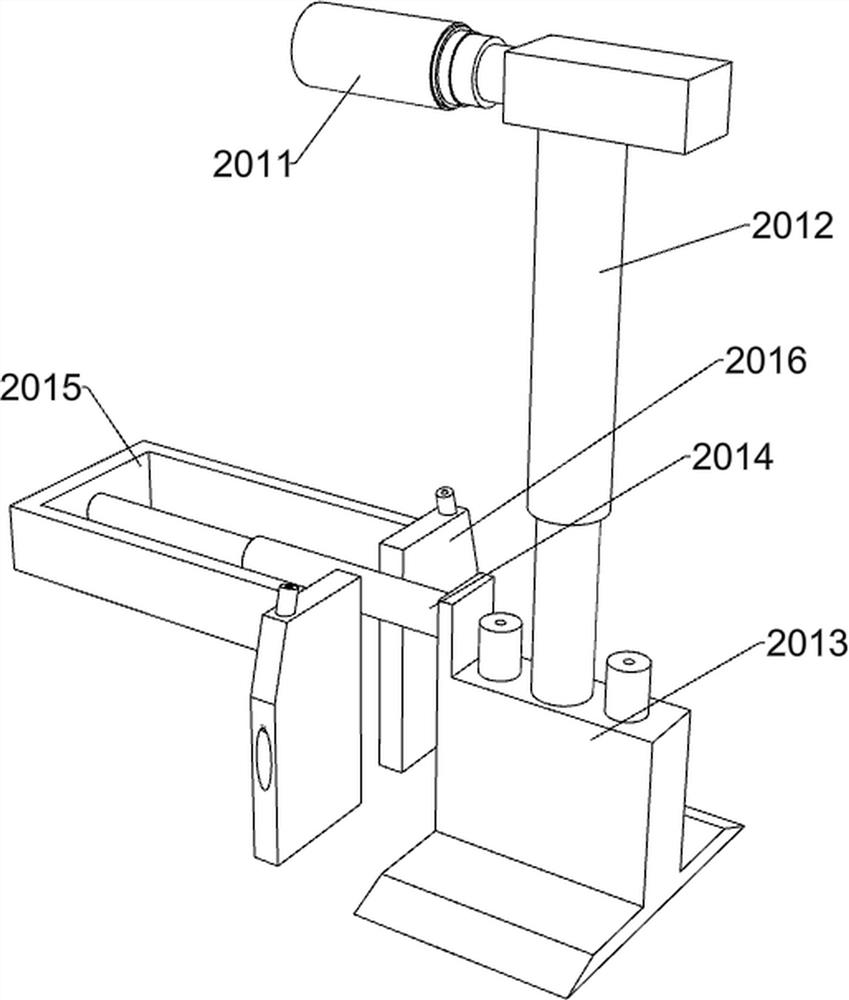
[0033] A protective grid installation device for road construction, such as Figure 1-2 As shown, it includes a chassis 1, a mounting assembly, a positive positioning assembly, a control panel 5, a first bottom plate 6, a second bottom plate 7, a first electric slide rail 8, a first slider 9, and a first multi-stage electric telescopic rod 10. The first electric clamp 11 and the first wheel 12; the middle part of the bottom frame 1 is installed with an installation component; the upper part of the bottom frame 1 is installed with an upright component; One side of the chassis 1 is affixed with a first base plate 6, and the other side of the upper surface of the chassis 1 is affixed with a second chassis 7; the upper part of the chassis 1 is affixed with a first electric slide rail 8; There are four sets of first wheels 12; the first electric slide rail 8 is slidingly connected with the first slider 9; the first multi-stage electric telescopic rod 10 is fixedly connected under t...


PUM


Abstract

The invention relates to the field of road construction, in particular to a protective grid mounting device for road construction. The technical problem to be solved by the invention is to provide the protective grid mounting device for road construction. According to the technical scheme, the protective grid mounting device for road construction comprises a mounting assembly, a position correcting assembly, a control screen and the like; a first sliding block is slidably connected into the first electric sliding rail; a first multi-stage electric telescopic rod is fixedly connected to the lower portion of the first sliding block; and a first electric clamp is fixedly connected below the first multi-stage electric telescopic rod. When the device is used, sand in a preset groove is automatically removed completely, two grid plates are installed in the preset groove at the same time, meanwhile, the phenomenon that the grid plates tilt up in the clamping process can be avoided, meanwhile, the phenomenon that the edges are broken due to the fact that the two grid plates incline and extrude in the transportation process can be prevented, the rebars on the vertical beam can be automatically corrected, and the joints of the rebars and the vertical beam can be supplemented, so that the stability is improved.

Description

technical field [0001] The invention relates to the field of road construction, in particular to a protective grid installation device for road construction. Background technique [0002] In the prior art, one of the road constructions needs to install a protective grid on the side of the road to ensure the normal construction. One of the protective grids is made of cement concrete, which is in the shape of a rectangular parallelepiped plate as a whole, and the rectangular parallelepiped plate etc. Rectangular through holes are provided at the distance. When installing such protective grids in existing devices, two pieces of protective grids are hoisted into the preset grooves in turn, and preset vertical beams are set on both sides of the preset grooves to reserve intervals. Only two centimeters, a slight deviation in the position of the first protective grid will make it difficult to install the second protective grid. In addition, when the two protective grids are install...

Claims


Application Information

Patent Timeline
Patent Type & Authority Applications(China)
IPC IPC(8): E01C19/52
CPCE01C19/52
Inventor 张彬
Owner 张彬
Learn More