Optical system, lens module and electronic equipment

An optical system and lens technology, applied in optics, optical components, instruments, etc., can solve problems affecting the screen-to-body ratio of electronic equipment, difficult to meet the design requirements of high screen-to-body ratio of electronic equipment, and affecting the opening size of the display screen, etc.

Active Publication Date: 2021-11-09
JIANGXI JINGCHAO OPTICAL CO LTD
View PDF4 Cites 5 Cited by
  • Summary
  • Abstract
  • Description
  • Claims
  • Application Information

AI Technical Summary

Problems solved by technology

For electronic devices with off-screen camera functions, the size of the camera lens affects the opening size of the display screen, which in turn affects the screen-to-body

Method used


Image

  • Optical system, lens module and electronic equipment
  • Optical system, lens module and electronic equipment
  • Optical system, lens module and electronic equipment

Examples


no. 1 example

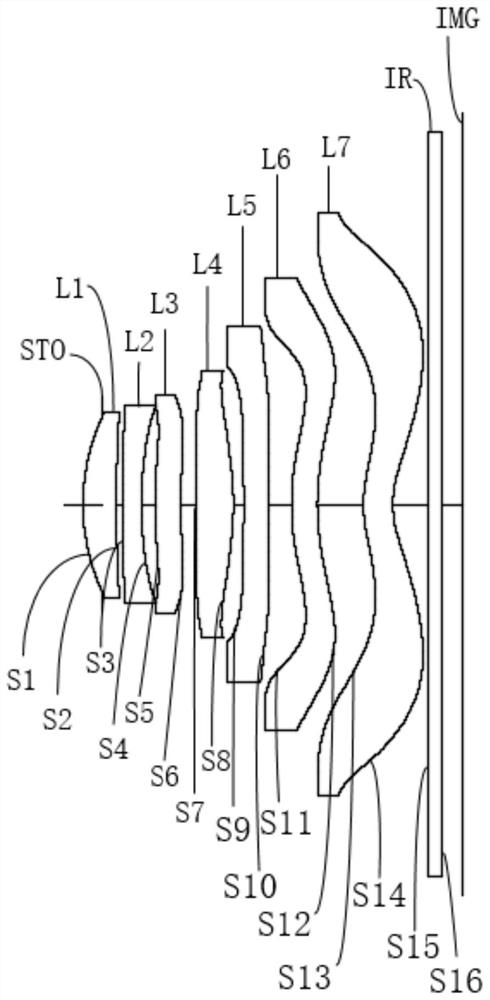
[0040] Please refer to figure 1 and figure 2 , the optical system of this embodiment includes in sequence from the object side to the image side along the optical axis direction:

[0041] The first lens L1 has positive refractive power. The object side S1 of the first lens L1 is convex at the near optical axis, and the image side S2 of the first lens L1 is concave at the near optical axis.

[0042] The second lens L2 has a negative refractive power. The object side S3 of the second lens L2 is convex at the near optical axis, and the image side S4 of the second lens L2 is concave at the near optical axis.

[0043] The third lens L3 has positive refractive power. The object side S5 of the third lens L3 is convex at the near optical axis, and the image side S6 of the third lens L3 is concave at the near optical axis.

[0044] The fourth lens L4 has positive refractive power. The object side S7 of the fourth lens L4 is concave at the near optical axis, and the image side S8 of ...

no. 2 example

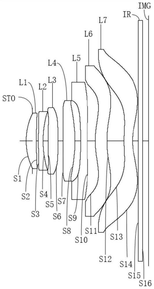
[0065] Please refer to image 3 and Figure 4 , the optical system of this embodiment includes in sequence from the object side to the image side along the optical axis direction:

[0066] The first lens L1 has positive refractive power. The object side S1 of the first lens L1 is convex at the near optical axis, and the image side S2 of the first lens L1 is concave at the near optical axis.

[0067] The second lens L2 has a negative refractive power. The object side S3 of the second lens L2 is convex at the near optical axis, and the image side S4 of the second lens L2 is concave at the near optical axis.

[0068] The third lens L3 has positive refractive power, and both the object side S5 and the image side S6 of the third lens L3 are convex at the near optical axis.

[0069] The fourth lens L4 has positive refractive power, and both the object side S7 and the image side S8 of the fourth lens L4 are convex at the near optical axis.

[0070] The fifth lens L5 has negative r...

no. 3 example

[0083] Please refer to Figure 5 and Figure 6 , the optical system of this embodiment includes in sequence from the object side to the image side along the optical axis direction:

[0084] The first lens L1 has positive refractive power. The object side S1 of the first lens L1 is convex at the near optical axis, and the image side S2 of the first lens L1 is concave at the near optical axis.

[0085] The second lens L2 has a negative refractive power. The object side S3 of the second lens L2 is convex at the near optical axis, and the image side S4 of the second lens L2 is concave at the near optical axis.

[0086] The third lens L3 has positive refractive power. The object side S5 of the third lens L3 is convex at the near optical axis, and the image side S6 of the third lens L3 is concave at the near optical axis.

[0087] The fourth lens L4 has positive refractive power, and both the object side S7 and the image side S8 of the fourth lens L4 are convex at the near optical...


PUM


Abstract

The invention discloses an optical system, a lens module andelectronic equipment. The optical system sequentially comprises from an object side to an image side along an optical axis: first to seventh lenses having refractive power, wherein the first, fourth and sixth lenses have positive refractive power, and the second and seventh lenses have negative refractive power; the object-side surfaces of the first, second, sixth and seventh lenses are convex in a paraxial region, and the image-side surfaces of the second, sixth and seventh lenses and the object-side surface of the fifth lens are concave in a paraxial region; the optical system satisfies the following relational expressions: 1.1 < SD11/tan (HFOV) < 1.5, and HFOV>42 degrees, wherein the SD11 is the maximum effective half aperture of the object side surface of the first lens, and the HFOV is half of the maximum field angle of the optical system. By reasonably designing the surface type and the refractive power of each lens and satisfying the relational expression, the small-head design is realized while the good camera shooting performance is maintained, so that the design requirement of high screen-to-body ratio of the electronic equipment is met.

Description

technical field [0001] The invention belongs to the technical field of optical imaging, and in particular relates to an optical system, a lens module and electronic equipment. Background technique [0002] With the development of camera technology, more and more electronic devices place the camera lens under the display screen to realize the design of the camera function under the screen. At the same time, due to the increasing market demand for electronic devices with high screen-to-body ratios, the industry has been devoting itself to the design of high-screen-to-body ratio electronic devices. For an electronic device with an off-screen camera function, the size of the camera lens affects the aperture size of the display screen, which in turn affects the screen-to-body ratio of the electronic device. However, the size of the current optical system is difficult to meet the design requirements of high screen-to-body ratio of electronic devices. Contents of the invention ...

Claims


Application Information

Patent Timeline
IPC IPC(8): G02B13/00G02B13/18
CPCG02B13/0015G02B13/0045G03B30/00
Inventor 曾晗刘秀李明
Owner JIANGXI JINGCHAO OPTICAL CO LTD
Why Eureka
Try Eureka