Magnet separator and motor

A spacer and magnet technology, applied in the direction of magnetic circuit rotating parts, magnetic circuit static parts, manufacturing motor generators, etc., can solve problems such as unfavorable automatic assembly, achieve good mechanical stability, easy to use, and easy to implement Effect

Pending Publication Date: 2021-11-09
OTIS ELEVATOR CO
View PDF0 Cites 0 Cited by
  • Summary
  • Abstract
  • Description
  • Claims
  • Application Information

AI Technical Summary

Problems solved by technology

[0003] However, existing magnet fixation solutions are not conducive to automated assembly and often require manual operations

Method used


Image

  • Magnet separator and motor
  • Magnet separator and motor
  • Magnet separator and motor

Examples


Embodiment Construction

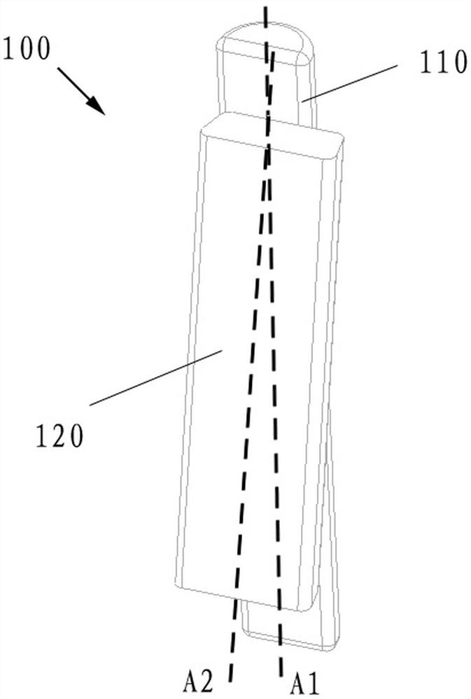
[0032] Preferred embodiments of the present application will be described in detail below with reference to the accompanying drawings. Those skilled in the art will appreciate that these descriptions are only descriptive and exemplary, and should not be construed as limiting the protection scope of the present application.

[0033] First of all, it should be noted that the orientation terms such as top, bottom, upward, and downward mentioned herein are defined relative to the directions in the respective drawings. These orientations are relative concepts, and thus will vary according to the location and state in which they are located. Accordingly, these or other directional terms should not be construed as limiting.

[0034] In addition, it should also be noted that for any single technical feature described or implied in the embodiments herein or any single technical feature shown or implied in the drawings, these technical features (or their equivalents) Combinations can ...


PUM


Abstract

The invention provides a magnet separator and a motor. The magnet separator includes a first joint part configured to extend along a first axis, and a second joint part which is configured to extend along a second axis and configured to be integrally formed with the first joint part, wherein a preset angle is formed between the first axis and the second axis; the shape of the first joint part is configured to be matched with the shape of a concave part in a motor rotor; and the shape of the side surface of the second joint part is configured to be matched with the shape of the side surface of a motor magnet. The magnet separator and the motor have the advantages of being simple, reliable, easy to implement, convenient to use and the like, automatic and rapid assembly of the motor can be achieved, and meanwhile good mechanical stability is provided.

Description

technical field [0001] The present application relates to the field of electrical machine construction. More specifically, the present application relates to a magnet spacer intended to provide convenient and flexible assembly of motor magnets. The present application also relates to an electric machine comprising the above-mentioned magnet spacer. Background technique [0002] For a motor in which a stator is mounted on a motor axis and a rotor is arranged to rotate around the motor axis, motor magnets need to be mounted to the rotor in the circumferential direction of the rotor. For example, a plurality of motor magnets may be arranged on a certain cross-section of the rotor. Existing motor magnets are usually fixed by means of glue and mechanical fixation. Glue can be an adhesive that needs to be cured at high temperature, while mechanical fixation is usually achieved with components such as bolts. [0003] However, existing magnet fixing solutions are disadvantageous...

Claims


Application Information

Patent Timeline
Patent Type & Authority Applications(China)
IPC IPC(8): H02K1/27
CPCH02K1/2791H02K2201/06H02K1/274H02K15/03H02K1/18
Inventor 李亚涛
Owner OTIS ELEVATOR CO
Why Eureka
Try Eureka