Storage equipment for precious oil painting collection and protection device for storage equipment
A protection device and oil painting technology, applied in the field of art supplies, can solve the problems of inability to appreciate oil paintings and low protection of oil paintings, and achieve the effects of realizing storage stability, improving storage effect and improving protection performance.
- Summary
- Abstract
- Description
- Claims
- Application Information
AI Technical Summary
Problems solved by technology
Method used
Image
Examples
Embodiment 1
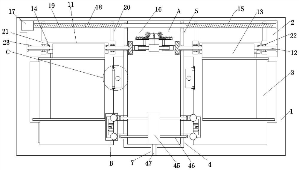
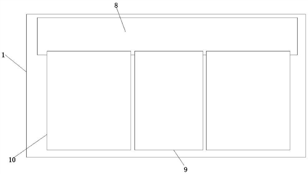
[0029] Embodiment one, by Figure 1 to Figure 3 Provided, a preservation device for precious oil painting collection, comprising a preservation box 1, the inner top of the preservation box 1 is provided with an accommodating tank 2, and the inner bottom of the preservation box 1 is symmetrically provided with two oil painting exhibition tanks 3, and the two Offer to place groove 4 between two oil painting exhibition grooves 3, place the inside of groove 4 to be provided with and place box 5, all be connected by two stomatal passages 6 between place box 5 and two oil painting exhibition grooves 3, place box 5 The middle position of the bottom end is provided with the exhaust duct 7 that runs through the outside of the storage box 1, the outside of the storage box 1 is provided with a baffle plate 8 positioned at one side of the storage tank 2, and one side of the oil painting exhibition tank 3 is provided with a storage tank. The observation window 10 that casing 1 connects, on...
Embodiment 2
[0030] Embodiment two, on the basis of embodiment one, byfigure 1 Given, the clamping mechanism 15 includes a motor one 17, a rotating shaft 18, a two-way threaded section 19, a slider 20, a collar 21, a clamping rod 22, a connecting shaft 23 and a gear one 24, and the motor one 17 is installed in the receiving groove 2 On one side, the output shaft of motor one 17 is connected with the rotating shaft 18 that runs through the two side walls of the placement box 5 and is connected with the inner wall of the receiving tank 2 in rotation. , and two two-way threaded sections 19 are connected with two sliders 20, and the bottom ends of the sliders 20 are provided with collars 21, and the collars 21 are rotatably connected with clamping rods that snap into the clamping grooves 14 22, one end of the clamping rod 22 is connected with a connecting shaft 23, wherein two connecting shafts 23 are movably connected with the inner wall of the receiving groove 2, and wherein the other two con...
Embodiment 3
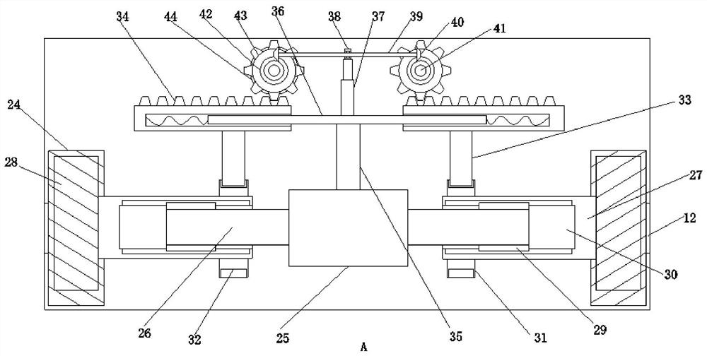
[0032] Embodiment three, on the basis of embodiment one, by image 3 Given, the transmission mechanism 16 includes a transmission group, a moving group and a driving group, and the transmission group includes a biaxial motor 25, a rotating shaft 26, a rotating cylinder 27, a gear 28, a clipping plate 29 and a clipping groove 30, and the biaxial motor 25 Installed in the inside of the placement box 5, the output shaft of the biaxial motor 25 is connected with a rotating shaft 26, and one end of the rotating shaft 26 is rotatably connected with a rotating cylinder 27, and one end of the rotating cylinder 27 is provided with a gear two meshed with the gear one 24 28, and the gear two 28 is connected with the curtain rewinding shaft 12, and one end of the rotating shaft 26 is provided with a clamping plate 29, and the inside of the rotating cylinder 27 is provided with a clamping groove 30 that is clamped with the clamping plate 29, and the moving group Including a rotating wheel ...
PUM
 Abstract
Description
Claims
Application Information
 - R&D
- Intellectual Property
- Life Sciences
- Materials
- Tech Scout
- Unparalleled Data Quality
- Higher Quality Content
- 60% Fewer Hallucinations
Browse by: Latest US Patents, China's latest patents, Technical Efficacy Thesaurus, Application Domain, Technology Topic, Popular Technical Reports.
© 2025 PatSnap. All rights reserved.Legal|Privacy policy|Modern Slavery Act Transparency Statement|Sitemap|About US| Contact US: help@patsnap.com


