
Bent pipe type vibration reduction connecting pipe measuring device and method

A technology for measuring devices and pipe bends, applied in measuring devices, mechanical measuring devices, mechanical devices, etc., to achieve the effects of ensuring accuracy, convenient installation and positioning, and easy operation

Pending Publication Date: 2021-11-12
中国船舶集团渤海造船有限公司
View PDF9 Cites 1 Cited by
  • Summary
  • Abstract
  • Description
  • Claims
  • Application Information

AI Technical Summary

Problems solved by technology

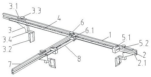
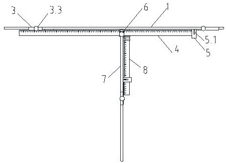
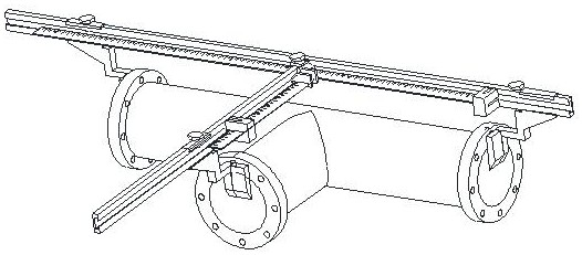
By installing the clamping and positioning mechanism on the measuring frame and using the clamping and positioning mechanism to assemble the measuring frame on the elbow-type vibration-damping joint, by measuring the difference between the axis and the center line of the elbow-type vibration-damping joint before and after installation Make a judgment on whether the installation is qualified, solve the technical problem of using the axis and centerline of the elbow-type vibration-damping joint as the measurement target to complete the intuitive quantitative transfer and judge whether the installation meets the standard through the difference obtained from the measurement

Method used


Image

  • Bent pipe type vibration reduction connecting pipe measuring device and method
  • Bent pipe type vibration reduction connecting pipe measuring device and method
  • Bent pipe type vibration reduction connecting pipe measuring device and method

Examples


Embodiment Construction

[0020] The following will clearly and completely describe the technical solutions in the embodiments of the present invention with reference to the accompanying drawings in the embodiments of the present invention. Obviously, the described embodiments are only some, not all, embodiments of the present invention. Although the embodiments of the present invention have been shown and described, those skilled in the art can understand that various changes, modifications and substitutions can be made to these embodiments without departing from the principle and spirit of the present invention. and modifications, the scope of the invention is defined by the appended claims and their equivalents. Based on the embodiments of the present invention, all other embodiments obtained by persons of ordinary skill in the art without making creative efforts belong to the protection scope of the present invention.

[0021] As shown in the figure, the straight pipe section measuring frame 1 is s...


PUM


Abstract

The invention provides an bent pipe type vibration reduction connecting pipe measuring device and method. The device comprises a straight pipe section measuring frame, a bent pipe section measuring frame and a clamping and positioning mechanism, wherein the straight pipe section measuring frame is in a long strip shape, a straight pipe section customized ruler used for measuring the axis of a straight pipe is fixedly arranged on the straight pipe section measuring frame, the straight pipe section measuring frame is movably provided with two opposite clamping and positioning mechanisms and is movably provided with an anchoring piece, the bent pipe section measuring frame which is horizontally perpendicular to the straight pipe section measuring frame and is the same as the straight pipe section measuring frame in structure is installed on the straight pipe section measuring frame in a sliding mode through a bent pipe section measuring frame connecting assembly, a bent pipe section customized ruler used for measuring the center line of a bent pipe is fixedly arranged on the bent pipe section measuring frame, and the clamping and positioning mechanisms and the anchoring piece are movably installed on the bent pipe section measuring frame. According to the invention, the axis and the center line of the elbow type vibration reduction connecting pipe are taken as measurement targets to complete visual quantitative transfer, and whether the installation meets the standard is judged according to the difference value obtained through measurement; and the elbow type vibration reduction connecting pipe measuring device and method are suitable for being used as the elbow type vibration reduction connecting pipe measuring device and method.

Description

technical field [0001] The invention relates to a measuring device and method in the technical field of ship pipeline installation, in particular to a measuring device and method for an elbow-type vibration-damping joint. Background technique [0002] As a new type of vibration damping joint, the bent pipe type vibration damping joint has the characteristics of large working pressure bearing capacity, strong displacement balance ability in all directions, etc., and has the function of damping vibration and noise, and is mainly used in ship steam pipeline systems. [0003] The elbow type vibration damping adapter is divided into a straight pipe section and an elbow section. When the elbow type vibration damping adapter is installed on the hull, it needs to meet the installation specifications, that is, when the installation is completed, the flange of the elbow section must reach the The distance from the axis of the straight pipe section relative to the original measured dim...

Claims


Application Information

Patent Timeline
Patent Type & Authority Applications(China)
IPC IPC(8): G01B5/30G01B5/25G01B5/14G01B5/00
CPCG01B5/30G01B5/25G01B5/14G01B5/00G01B5/0002
Inventor 白光道李清翟高鹏芦颖姜凯聂铭
Owner 中国船舶集团渤海造船有限公司
Learn More