Installation structure of electronic lock

An installation structure and electronic lock technology, which is applied in the application of locks, electric locks, building locks, etc., can solve the problems of poor reliability, limited versatility, easy deformation and looseness, etc., to improve reliability, improve versatility and interchangeability effect

Inactive Publication Date: 2008-09-03
曹湛斌
View PDF1 Cites 9 Cited by
  • Summary
  • Abstract
  • Description
  • Claims
  • Application Information

AI Technical Summary

Problems solved by technology

But the defect of this kind of structure is obvious, because it adopts U-shaped splint, the versatility of the installation and use of a splint under the situation of different door thicknesses is limited; Secondly, because the U-shaped splint is clamped on both sides of the door leaf, The unilateral tightening method is adopted, although it has the characteristics of easy installation, but the reliability is very poor, and the splint must be made of expensive spring steel, otherwise it is easy to deform and loosen

Method used


Image

  • Installation structure of electronic lock
  • Installation structure of electronic lock
  • Installation structure of electronic lock

Examples


Embodiment 1

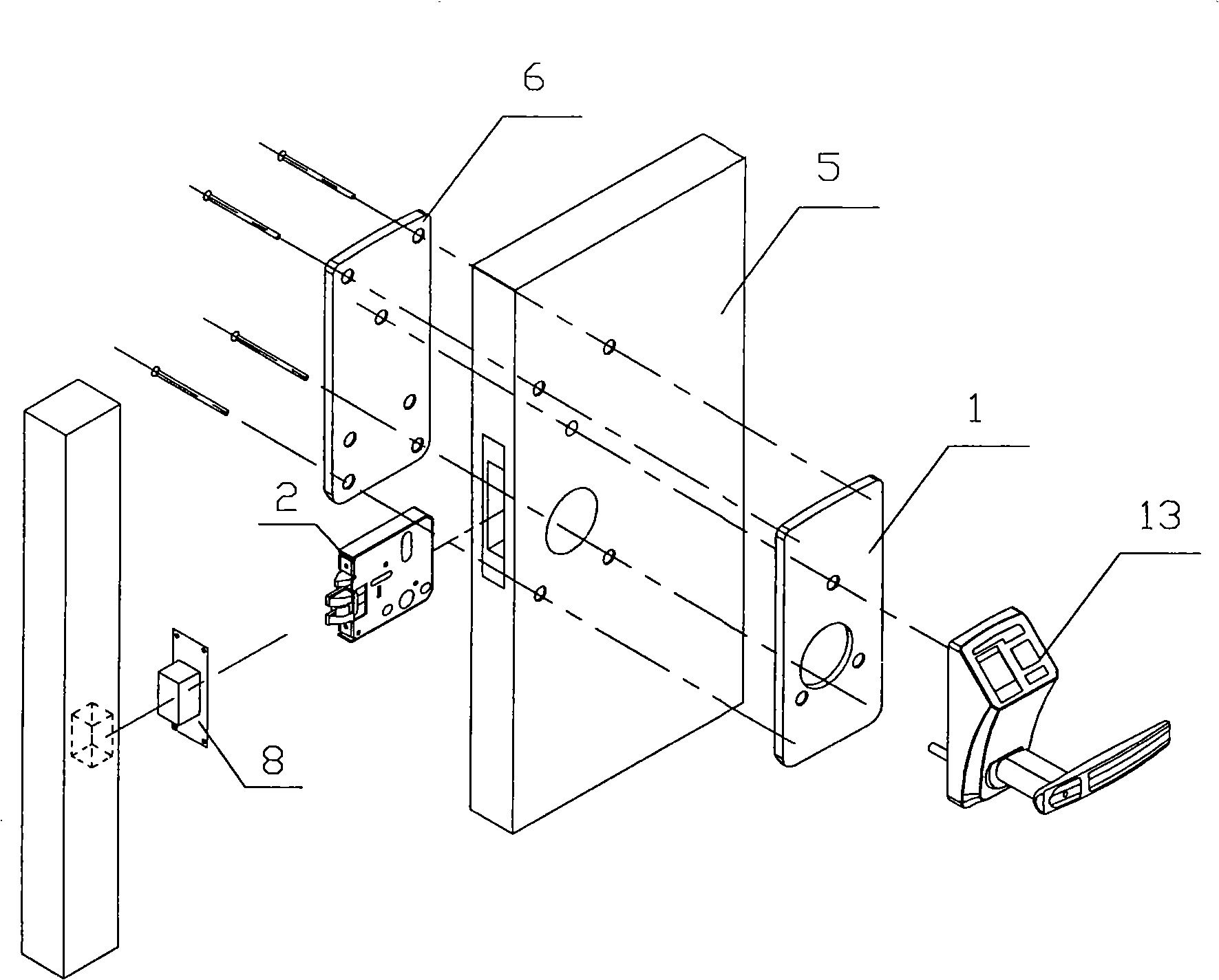
[0045] Such as figure 1 As shown, an installation structure for installing an electronic lock on a wooden door includes an electronic control unit box 13, an outer fixing plate 1, a lock body 2, an inner fixing plate 6, and a door leaf 5. The outer fixing plate 1 and the inner fixing plate 6 are Flat.

[0046] The lock body 2 is fixed in the middle of the door leaf 5 between the inner fixing plate 6 and the outer fixing plate 1, and the inner fixing plate 6 and the outer fixing plate 1 are tightly clamped on the door leaf 5 with screws. The electronic control unit box 13 is fixed on the outer surface of the outer fixing plate 1. The buckle box 8 corresponding to the lock body 2 is fixed on the door frame at the corresponding position. Of course, before installation, the user needs to make holes or slots in the corresponding positions of the door leaf 5, the inner fixing plate 6 or the outer fixing plate 1 according to the installation drawing of the electronic control unit box, a...

Embodiment 2

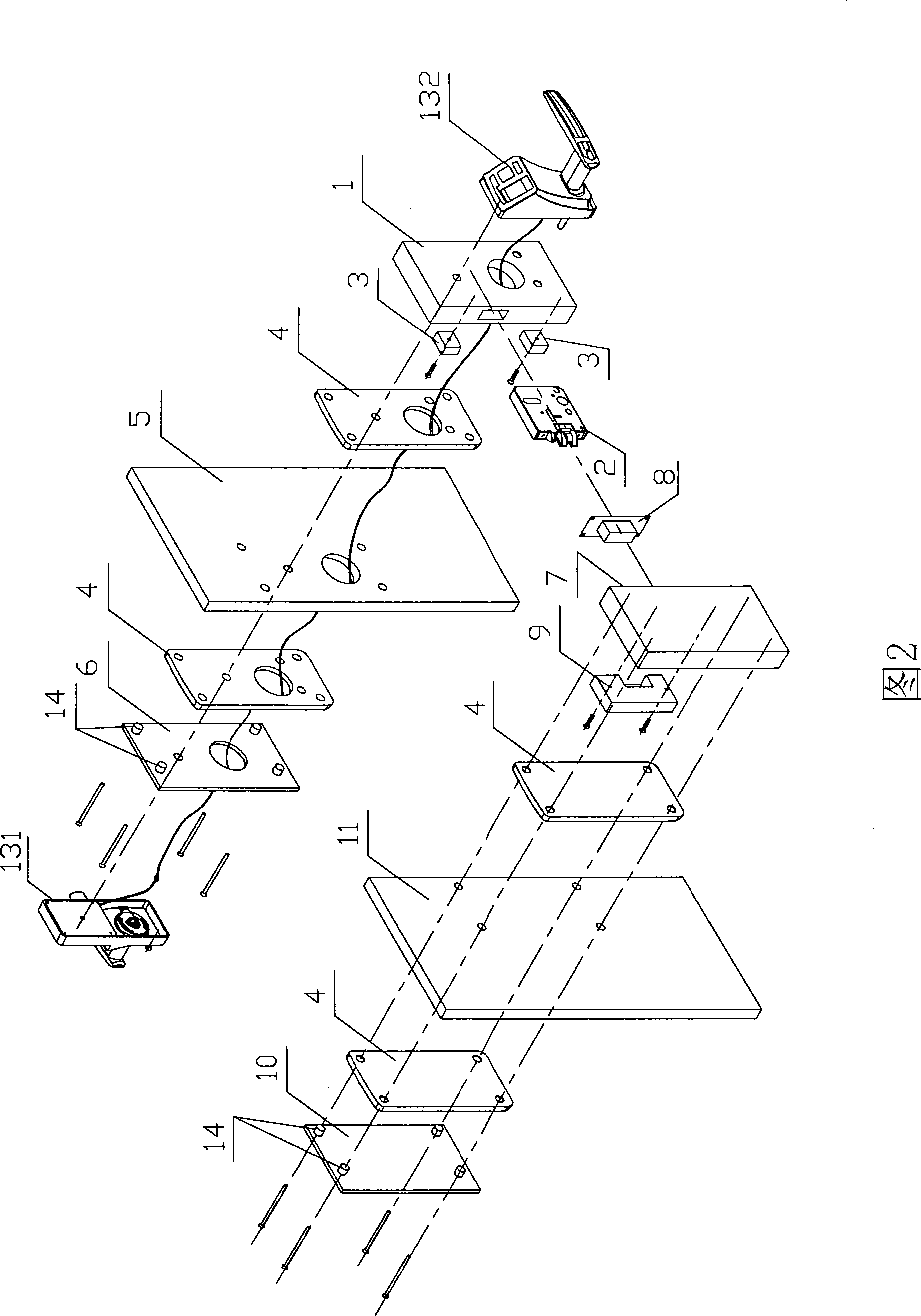
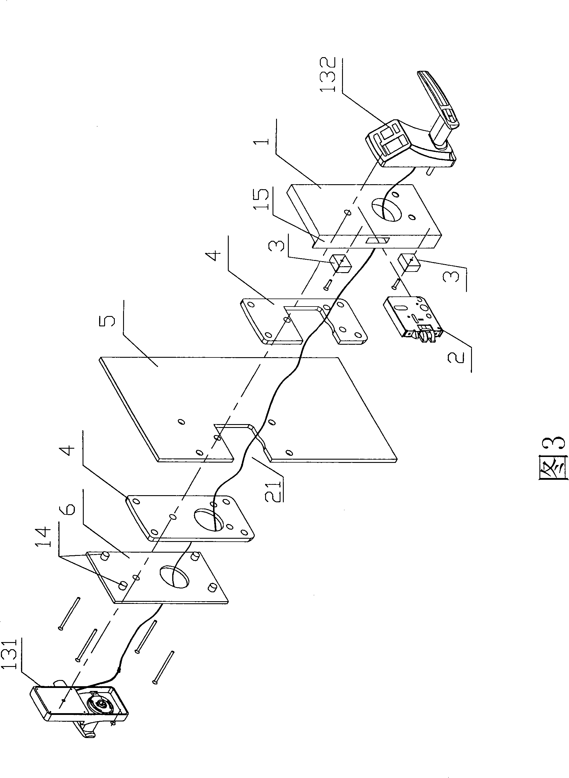
[0048] As shown in Figure 2, an installation structure for installing an electronic lock on a double-door glass door includes an electronic control unit box 13, an outer fixing plate 1, a lock body 2, a positioning bracket 3, a non-slip sealing cushion 4, and an inner fixing Board 6. The electronic control unit box includes an inner lock unit box 131 of the electronic control unit box and an outer accessory unit box 132 of the electronic control unit box; the inner fixed plate 6 is in the shape of a flat plate. The lock body 2 is equipped with a buckle box 8 correspondingly, and the corresponding settings are: a buckle box bracket 9 for installing the buckle box 8, an outer panel 7, and an inner panel 10. The electronic control unit box and the lock body 2 are installed on the right glass door leaf 5, and the buckle box 8 is installed on the corresponding left glass door leaf 11.

[0049] Such as Figure 4 As shown, the four peripheries of the outer fixing plate 1 are provided wit...

Embodiment 3

[0054] Such as Figure 7 , Figure 8 , Picture 9 As shown, the difference from the first and second embodiments is that the outer fixing plate 1 and the inner fixing plate 6 are provided with a wide fold 16 on one side, the cross section of which is in the shape of "L", the inner fixing plate 6 and the outer fixing plate 1 The wide folds 16 are butted with each other at the buckling position of the end face of the door leaf 5, so that the overall appearance is consistent and more beautiful.


PUM


Abstract

The present invention discloses an installation structure of an electronic lock which comprises an electronic control unit box. The invention is characterized in that the structure also comprises two separated inner fixing plate and external fixing plate. The inner fixing plate and the external fixing plate can traverse the door leaf through the fastener and are oppositely installed and fixed on two sides of the door leaf. The electronic control unit box is detachably fixed on the external surface of the external fixing plate or the inner fixing plate. The invention has the characteristics of simple structure, convenient and reliable installation, wider installation range of the electronic lock and the like. The invention is widely applied on the installation of the electronic lock in various kinds of door, the installation of traditional core inserting door lock and the improvement and change of the old lock.

Description

Technical field [0001] The invention relates to an installation structure of an electronic lock. Background technique [0002] Electronic locks such as IC card locks, password locks, fingerprint locks, etc. have been developed in recent years as a new safe, convenient, and fashionable lock, which is more and more widely used. Many offices and shops have chosen to install electronic locks as their Safety protection equipment, the electronic control unit (box) of the general electronic lock is directly fixed and installed on the outer surface of the wooden door or steel door, and the mortise lock body is installed in the door leaf; and it is basically impossible to install the plug on the glass door. Electronic lock with core lock body. The main defect of this simple installation structure is poor safety performance, especially when it is installed on a wooden door. Due to the soft material of the wooden door, the electronic control unit (box) of the electronic lock is easily loose...

Claims


Application Information

Patent Timeline
Patent Type & Authority Applications(China)
IPC IPC(8): E05B49/00
Inventor 曹湛斌杨德容
Owner 曹湛斌
Why Eureka
Try Eureka