Method and system for multilevel serializer/deserializer

Inactive Publication Date: 2008-03-11
KATZMAN VLADIMIR +1
View PDF6 Cites 22 Cited by
  • Summary
  • Abstract
  • Description
  • Claims
  • Application Information

AI Technical Summary

Benefits of technology

[0007]A serial data bit transferring technique is provided. The technique eliminates the bit ambiguity problem of a standard time-division multiplexing / demultiplexing architecture without introduction of additional latency by alignment of an incoming serial data word at the DESerializer (DES) side based on marking pulses of increased amplitude imposed onto the data bit stream by the SERializer (SER) to mark positions of the out-going serial data words. The serializer includes two MUltipleXer (MUX) blocks with ratios N:L and L:1 converting N-bit wide parallel input data words with rate B into a serial data bit stream with rate NB and controlled by timing signals from an internal serializer timing circuit (SER_TC) with two user-selectable High-Frequency (HF) or Low-Frequency (LF) modes of synchronization.
[0008]An output Multilevel Buffer (MB) retimes the serialized data and increases the amplitude of certain bits with a preselected value at the positions specified by a SERializer Digital Data Converter (SER_DDC). The SER_DDC also encodes the L-bit wide data words after the first MUX block to provide a near-equal probability of logic “1” and logic “0” values in the output data stream thus effectively eliminating its low-frequency spectral components and ensuring regular appearance of the marking pulses with increased amplitude in direct and / or inverted output signals transmitted into single-ended or differential fiber-optic, copper or any other interconnect media. The imposed marking pulses are retrieved from the input serial data stream with bit rate NB received by an Input Detector (ID) of a DESerializer Timing Circuit (DES_TC) and used to either preset dividers of the circuit or provide a reference to its internal clock-recovery circuit, depending on the user-selected synchronization mode. The incoming serial data stream is retimed by the reconstructed HF clock and deserialized into N-bit wide parallel words with predetermined bit order by two DeMUltipleXer (DMUX) blocks with ratios 1:L and L:N controlled by signals from the deserializer timing circuit aligned to the marking pulses. The encoded L-bit wide parallel words after the first DMUX are decoded to its original bit values by a DESerializer Digital Data Converter (DES_DDC) also controlled by aligned signals from the timing circuit. As a result, the deserializer can directly reconstruct the original bit order and values from the serial data bit stream with no extra bits and maximum rate NB, thus providing minimal possible latency.

Problems solved by technology

The presence of extra bits increases the system latency and results in higher transmission frequency requirements.
Various transmission protocols, such as Infiniband, 3GIO, Gigabit Ethernet, SONET / SDH, etc. have been devised to establish the synchronization, but all of them require additional expensive circuitry and / or software for operation.

Method used


Image

  • Method and system for multilevel serializer/deserializer
  • Method and system for multilevel serializer/deserializer
  • Method and system for multilevel serializer/deserializer

Examples


Embodiment Construction

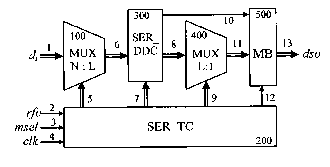
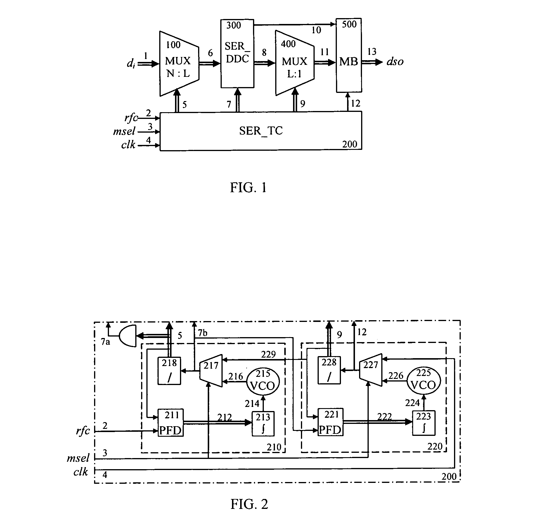
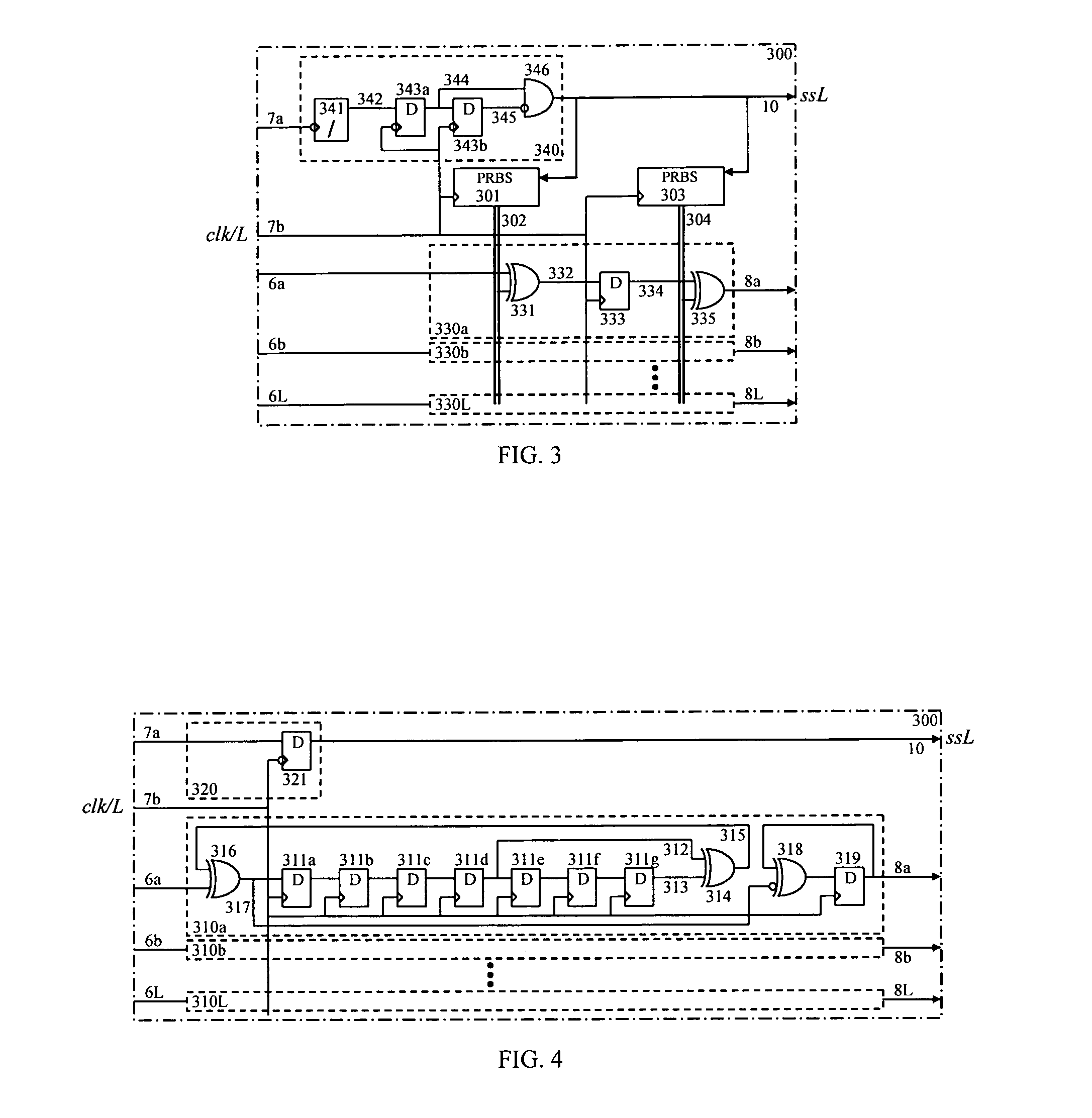
[0030]FIG. 1 is a block diagram and FIG. 5 is a timing diagram for a serializer in accordance with an exemplary embodiment of the present invention. Referring now to FIG. 1, input parallel low speed data words di 1 are applied to the input of MUX N:L 100. MUX N:L converts the N-bit wide parallel words di with rate B into L-bit wide parallel data words 6 with rate NB / L (e.g. 2B, 4B, etc.) under control of timing signals 5 generated by SER_TC block 200. Data words 6 are encoded by SER_DDC block 300 in order to achieve a near-equal probability of logic “1” and logic “0” values in the output data stream dso 13. SER_DDC 300 also generates L-bit long synchronization pulses ssL 10 to indicate desired positions of marking pulses in the out-going serial data 13.

[0031]All operations performed by SER_DDC 300 are controlled by timing signals 7 generated by SER_TC 200. The encoded data words 8 from SER_DDC 300 are further multiplexed into a serial data stream 11 by MUX L:1 400 under control of t...


PUM


Abstract

A serial bit transparent data transferring technique eliminating the bit ambiguity problem of the standard time-division multiplexing / demultiplexing architecture without introduction of any extra latency. A serializer multiplexer converts input parallel data words into a serial data bit stream under control of a serializer timing circuit. An output multilevel buffer retimes the serialized data and increases the amplitude of certain bits with a preselected value to mark positions of out-going serial data words. The bits are defined by a serializer digital data converter also controlled by the same timing circuit. The imposed marking pulses are retrieved from the input serial data stream by a multilevel input detector of a deserializer timing circuit and used for the synchronization of the demultiplexing operation. As a result, the deserializer directly reconstructs the original bit order from the serial data bit stream with no extra bits, thus providing minimal possible latency and full data rate.

Description

BACKGROUND OF THE INVENTION[0001]The present invention relates generally to the field of digital data communications and more specifically to low-latency serializers / deserializers.[0002]Data exchange between different points of communication (e.g.: computers, processors, memory units, etc.) through a serial link may use a multiplexing operation performed by a multiplexer (MUX) at a transmitter side followed by an inverse demultiplexing operation performed be a demultiplexer (DMUX) at a receiver side.[0003]The MUX converts N-bit wide parallel data words di={d(i)1, d(i)2, . . . d(i)N} with bit rate B into a serial bit stream ds=( . . . ds(i−1)N, ds(i)1, ds(i)2, . . . ds(i)N, ds(i+1)1, . . . ) with rate NB under control of timing signals sel1, sel2, . . . selK generated by a transmitter circuitry. For a binary MUX with a tree architecture, the relation between the parallel word width and the number of timing signals is given by equation N=2K, the signal sel1 is equal to the line-rate c...

Claims


Application Information

Patent Timeline
IPC IPC(8): H03M9/00
CPCH03L7/18H03M9/00H04L7/033H03L2207/06
Inventor KATZMAN, VLADIMIRBRATOV, VLADIMIR
Owner KATZMAN VLADIMIR
Why Eureka
Try Eureka