

Modular pneumatic distribution assembly
a technology of pneumatic distribution and modules, which is applied in the direction of valve housings, servomotors, transportation and packaging, etc., can solve the problem of requiring the distributors of the smaller actuators in the group to be expensively overdimensioned
- Summary
- Abstract
- Description
- Claims
- Application Information
AI Technical Summary
Benefits of technology
Problems solved by technology
Method used
Image

Examples
Embodiment Construction
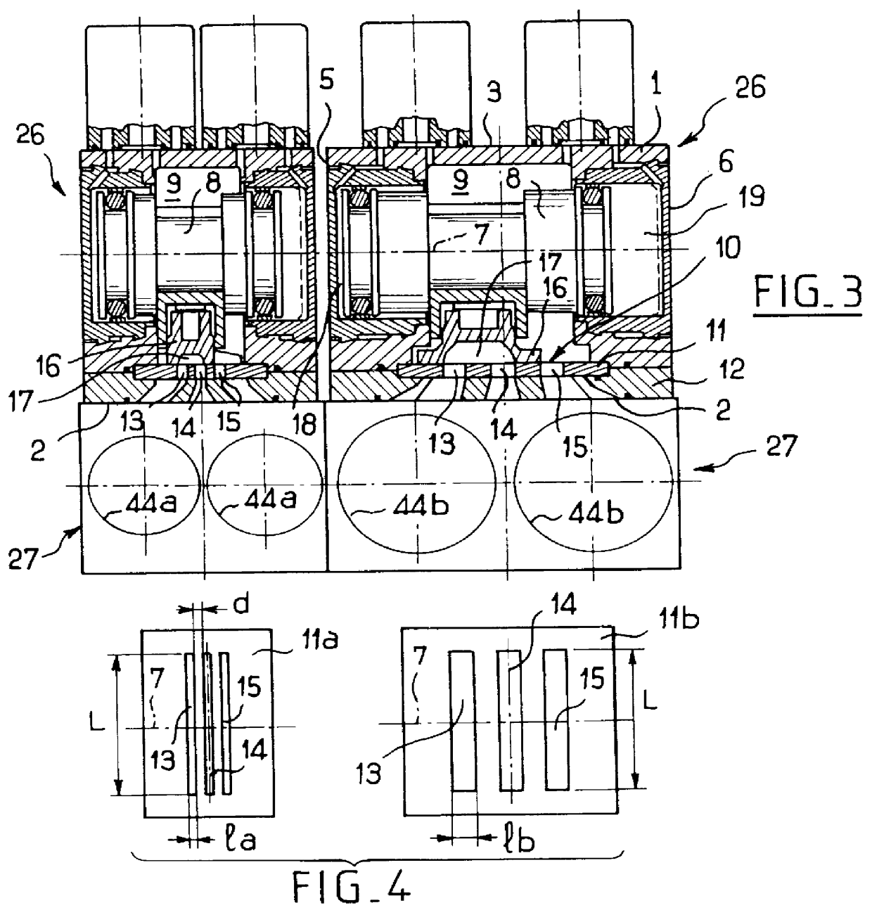
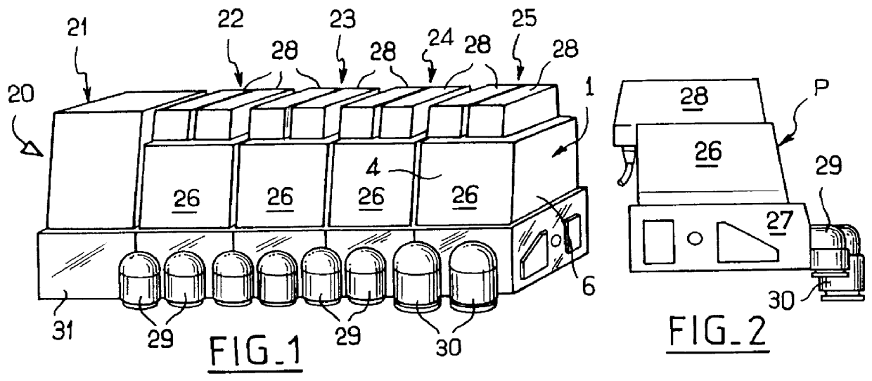
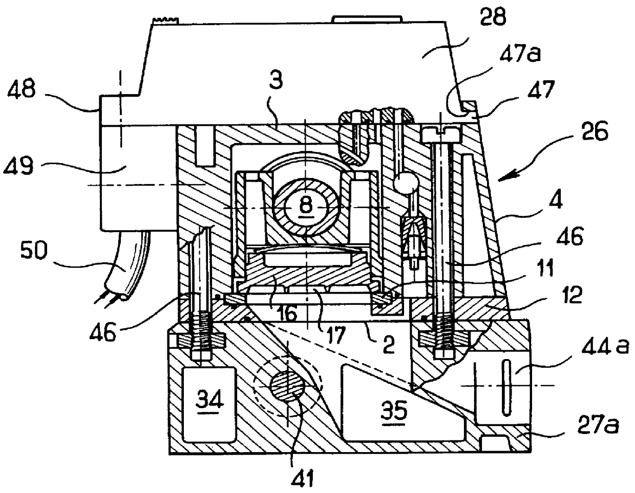
To begin with, the structure of a flat slide distributor is described. Such a distributor has a body 1 whose outside shape is generally in the form of a rectangular parallelepiped and which is defined by a bottom face 2 for association with a base, a top face 3 on which electrically-controlled pilot valves can be mounted, a front face 4, and two end faces 5 and 6 (FIGS. 1 and 3). The body 1 is provided with an internal hollow which includes cylindrical bearing surfaces for guiding a shaft 7 substantially perpendicularly to the end faces 5 and 6 and in which there is mounted a slide mechanism 8. Between the two bearing surfaces for guiding the slide mechanism, the internal hollow of the body 1 forms a chamber 9 which is defined by a side wall having a portion that presents a plane surface 10 directed towards the inside of the chamber 9. In conventional manner, this surface 10 is carried by a distribution plate 11 inserted in the body 1 between the main portion thereof and a distribut...
PUM
 Abstract
Description
Claims
Application Information