
A method of raised and engraving on a metallurgical board and a steel plate batch detection method

A technology of plates and steel plates, which is applied in the field of embossed markings on metallurgical plates, can solve the problems affecting the marking effect, metal splash, and affecting the quality of metallurgical plates, so as to ensure the marking accuracy and efficiency, the marking content is clear and accurate, and the marking fast effect

Active Publication Date: 2022-02-15
苏州市瑞思特智能制造有限公司
View PDF7 Cites 0 Cited by
  • Summary
  • Abstract
  • Description
  • Claims
  • Application Information

AI Technical Summary

Problems solved by technology

[0005] 1. The emitted laser has concentrated and continuous high energy, it is difficult to control the laser speed and energy, resulting in uncontrollable marking. For example, the thermal effect accompanying the processing process is easy to cause adverse damage to the metallurgical plate to be processed;
[0006] 2. Because the emitted continuous laser energy is too large, when the laser beam hits the metal surface, pits will be formed on the metal surface, causing part of the metal to melt, or even metal splashes, which will lead to uneven spots on the metallurgical plate to be processed. The pattern cannot guarantee the engraving of the basic lines, and it will also cause the cleanliness of the metallurgical plate to decline, affect the quality of the metallurgical plate, make the metallurgical plate need to be polished in the follow-up work, and the metal splash will directly affect the damage of the field mirror and affect the quality of the metallurgical plate. marking effect

Method used


Image

  • A method of raised and engraving on a metallurgical board and a steel plate batch detection method
  • A method of raised and engraving on a metallurgical board and a steel plate batch detection method
  • A method of raised and engraving on a metallurgical board and a steel plate batch detection method

Examples


Embodiment Construction

[0042]In order to enable those skilled in the art to better understand the solutions of the present invention, the following will clearly and completely describe the technical solutions in the embodiments of the present invention in conjunction with the drawings in the embodiments of the present invention. Obviously, the described embodiments are only It is an embodiment of a part of the present invention, but not all embodiments. Based on the embodiments of the present invention, all other embodiments obtained by persons of ordinary skill in the art without making creative efforts shall fall within the protection scope of the present invention.

[0043] It should be noted that the terms "first" and "second" in the description and claims of the present invention and the above drawings are used to distinguish similar objects, but not necessarily used to describe a specific sequence or sequence. It is to be understood that the data so used are interchangeable under appropriate c...


PUM

PropertyMeasurementUnit
diameteraaaaaaaaaa

Abstract

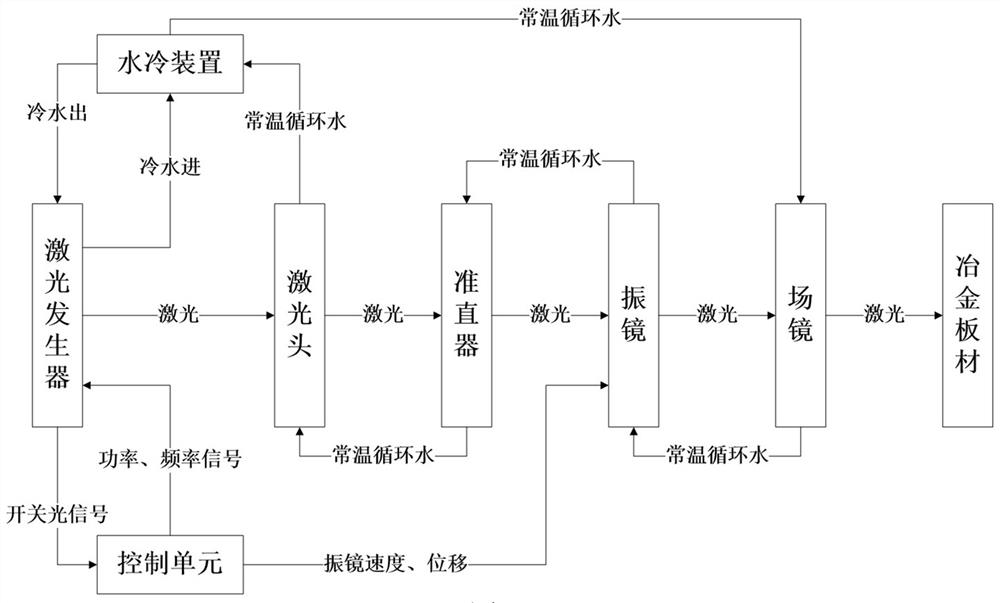
The invention discloses a method for embossing metallurgical plates and a batch detection method for steel plates. The method for embossing metallurgical plates in the engraving area uses a laser marking system to mark metallurgical plates. The laser marking system includes a laser, a vibration Mirror, field mirror, control unit, the laser emits laser light to the vibrating mirror, and the control unit controls the vibrating mirror according to the content to be marked so that the laser reflected by the vibrating mirror passes through the field mirror and projects to the corresponding position of the marking area, and the laser light reaching the marking area Make the surface of the metallurgical plate placed in the marking area display the marking content; the laser is a continuous laser, and the marking content is raised relative to the surface of the metallurgical plate. The method of raised marking includes setting the output power of the continuous laser within the range of 100W to 800W, And the working frequency of the continuous laser is set within the range of 10kHz to 60kHz. The invention realizes the convex marking on the surface of the metallurgical plate through the continuous laser, the marking content is clear and accurate, and the marking speed is fast.

Description

technical field [0001] The invention relates to the field of laser marking, in particular to a method for marking protrusions on metallurgical plates and a batch detection method for steel plates. Background technique [0002] With the improvement of domestic laser research and development technology and production and manufacturing capabilities, the quality level of lasers has improved, and the application fields of lasers have also expanded accordingly. At the same time, the application range in various fields is also expanding. Now, with the integration of industrialization and industrialization in metallurgical enterprises, metallurgical and smelting enterprises gradually have the need for product traceability and material code identification. It is urgent to solve the problems of fast marking and engraving material codes on hot steel billets or steel materials in metallurgical smelting, so as to realize product production. Process platform automation management. [000...

Claims


Application Information

Patent Timeline
Patent Type & Authority Patents(China)
IPC IPC(8): B23K26/362B23K26/70G01N21/84
CPCB23K26/362B23K26/702G01N21/84
Inventor 马鑫马刚马钰添
Owner 苏州市瑞思特智能制造有限公司
Learn More