A cutting device for glass fiber yarn production

A cutting device and glass fiber yarn technology, applied in the cutting of textile materials, textiles and papermaking, etc., can solve the problems affecting the use of glass fiber yarn, slow cutting speed, and skewed cutting, and achieve the effect of saving manpower

Active Publication Date: 2022-05-24
刘荣
View PDF0 Cites 0 Cited by
  • Summary
  • Abstract
  • Description
  • Claims
  • Application Information

AI Technical Summary

Problems solved by technology

[0006] In order to overcome the shortcomings of manual cutting of glass fiber yarns, the present invention needs to be extra cautious, the cutting speed is relatively slow, and the phenomenon of skewed cutting is still easy to occur, which affects the subsequent use of glass fiber yarns. The technical problem to be solved by the present invention is Provide a cutting device for glass fiber yarn production that does not need to cut glass fiber yarn manually and can cut glass fiber yarn smoothly

Method used


Image

  • A cutting device for glass fiber yarn production
  • A cutting device for glass fiber yarn production
  • A cutting device for glass fiber yarn production

Examples


Embodiment 1

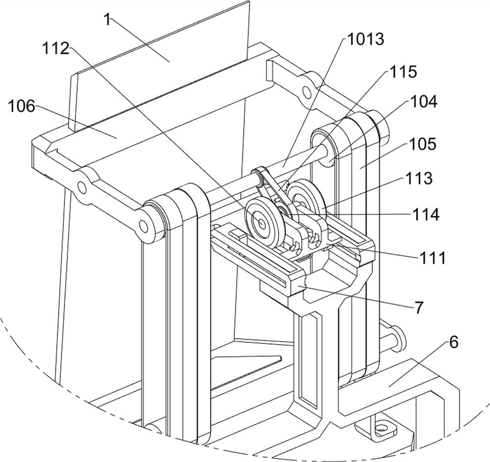
[0040] A cutting device for glass fiber yarn production, such as Figure 1-8As shown, it includes a base plate 1, a first connecting rod 2, a splint 3, a torsion spring 4, a discharge rod 5, a connecting frame 6, a guide rail 7, a cutter 8, a handle 9, a conveying mechanism 10 and a rotating mechanism 11, and the base plate 1 An anti-slip mat is installed at the bottom, which has an anti-slip effect. Two first connecting rods 2 are installed symmetrically on the upper part of the bottom plate 1. A discharge rod 5 is placed between the two first connecting rods 2. The discharge rod 5 is used to place Glass fiber yarn, the front side of the first connecting rod 2 is rotationally connected with a splint 3, the splint 3 is used to clamp the discharge rod 5, two torsion springs 4 are connected between the splint 3 and the first connecting rod 2, and the two torsion springs The spring 4 is left and right symmetrical, and the connecting frame 6 is installed on the front side of the b...

Embodiment 2

[0045] On the basis of Example 1, such as figure 1 , Figure 9 and Figure 10 As shown, a cutting mechanism 12 is also included, and the cutting mechanism 12 is used to drive the cutter 8, so that the cutter 8 can automatically cut the glass fiber yarn. The cutting mechanism 12 includes a rodless cylinder 121, a support rod 122 and a stabilizing plate 123 , a support rod 122 is installed on the rear side of the upper part of the connecting frame 6, a rodless cylinder 121 is connected between the top of the supporting rod 122 and the top of the connecting frame 6, and the rodless cylinder 121 is slidingly connected with the cutter 8, and the rodless cylinder 121 is used for driving Cutter 8, base plate 1 upper rear side is equipped with stabilizing plate 123, and stabilizing plate 123 is used for stabilizing glass fiber yarn, and stabilizing plate 123 is positioned at fixed rod 106 below.

[0046] like figure 1 , Figure 11 , Figure 12 and Figure 13 As shown, a stabiliz...

Embodiment 3

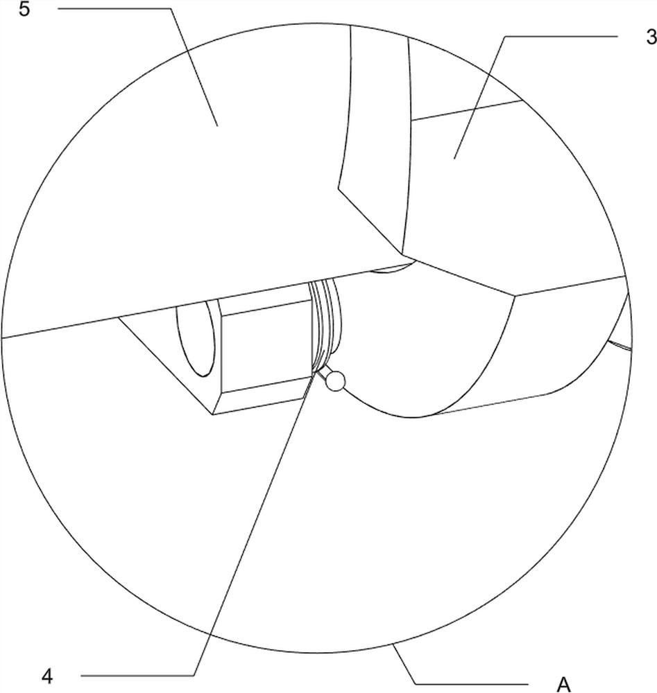
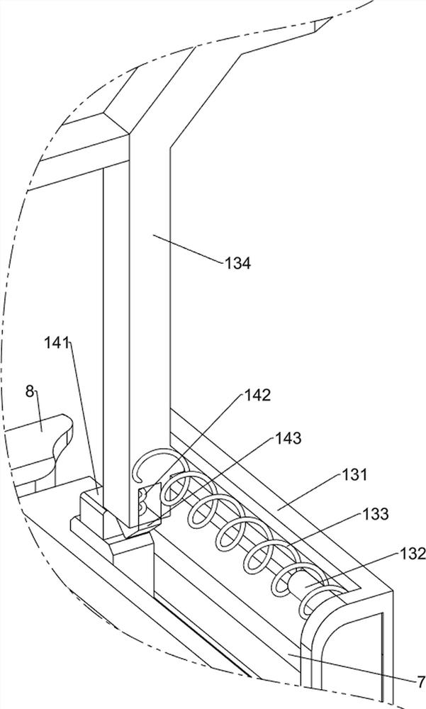
[0049] On the basis of Example 2, such as Figure 13 and Figure 14 Shown, also comprise push away mechanism 14, push away mechanism 14 is used for pushing away stabilizing mechanism 13, push away mechanism 14 includes second fixed block 141, the 4th spring 142 and wedge block 143, cutter 8 top left and right two sides Both sides are equipped with a second fixed block 141, the left and right sides of the bottom of the second connecting rod 134 are slidingly connected with wedge blocks 143, and the wedge block 143 cooperates with the second fixed block 141. A fourth spring 142 is connected, the top end of the fourth spring 142 is connected with the second connecting rod 134 , and the bottom end of the fourth spring 142 is connected with the wedge block 143 .

[0050] When the cutter 8 moves forward and resets, it will drive the second fixed block 141 to move forward, and the second fixed block 141 will move forward to drive the wedge-shaped block 143 to move forward, and the s...


PUM


Abstract

The invention relates to a cutting device, in particular to a cutting device for glass fiber yarn production. The invention provides a cutting device for glass fiber yarn production which does not need to cut the glass fiber yarn manually and can cut the glass fiber yarn smoothly. A cutting device for glass fiber yarn production, comprising a bottom plate, a first connecting rod, a splint, a torsion spring, a feeding rod, a connecting frame, a guide rail, a cutter, a handle, a conveying mechanism and a rotating mechanism, and the upper part of the bottom plate is arranged symmetrically. Two first connecting rods are installed, and the front side of the first connecting rod is rotatably connected with a splint. Two torsion springs are connected between the splint and the first connecting rod. The two torsion springs are left and right symmetrical. A discharge rod is placed between them, and a connecting frame is installed on the front side of the bottom plate. The rotating mechanism can drive the conveying mechanism to continuously transport the glass fiber yarn, and the user can cut the glass fiber yarn by pulling the cutter, realizing the function of flat cutting the glass fiber yarn.

Description

technical field [0001] The invention relates to a cutting device, in particular to a cutting device for glass fiber yarn production. Background technique [0002] Glass fiber yarn is a material made of glass fiber, which has the function of fire prevention and heat insulation. It can be used in different industries such as transportation, construction, petrochemical industry, etc. In order to meet different application requirements, it usually needs to be used in the production of glass fiber yarn Cut the fiberglass yarn. [0003] At present, the glass fiber yarn is mainly cut manually. When cutting, people first draw the size to be cut on the glass fiber yarn with a pen, and then manually hold the scissors to cut the glass fiber yarn along the drawn line. This manual cutting method needs to be extra cautious, the cutting speed is slow, and it is still prone to cutting skew, which affects the subsequent use of glass fiber yarn. [0004] Therefore, it is necessary to design...

Claims


Application Information

Patent Timeline
Patent Type & Authority Patents(China)
IPC IPC(8): D06H7/02
CPCD06H7/02
Inventor 刘荣
Owner 刘荣
Why Eureka
Try Eureka