
Lock with state detection function and state detection method using lock

A state detection and lock technology, applied in the field of power transmission and transformation, can solve problems such as status feedback and misoperation that are difficult to obtain whether the lock has been locked or unlocked, and achieve the effect of avoiding misoperation accidents and short circuit accidents.

Pending Publication Date: 2021-11-16
CYG CONTRON
View PDF0 Cites 1 Cited by
  • Summary
  • Abstract
  • Description
  • Claims
  • Application Information

AI Technical Summary

Problems solved by technology

[0003] In view of the above defects, an object of the present invention is to propose a lock with state detection, which solves the problem that the existing structure is difficult to obtain the state feedback of whether the lock has been locked or unlocked, resulting in misoperation accidents
[0004] In view of the above-mentioned defects, another object of the present invention is to propose a state detection method, which solves the problem that it is difficult to obtain the state feedback of whether the lock has been locked or unlocked in the existing method, thus leading to the problem of misoperation accidents

Method used


Image

  • Lock with state detection function and state detection method using lock
  • Lock with state detection function and state detection method using lock
  • Lock with state detection function and state detection method using lock

Examples


Embodiment Construction

[0056] Embodiments of the present invention are described in detail below, examples of which are shown in the drawings, wherein the same or similar reference numerals designate the same or similar elements or elements having the same or similar functions throughout. The embodiments described below by referring to the figures are exemplary only for explaining the present invention and should not be construed as limiting the present invention.

[0057] In describing the present invention, it should be understood that the terms "longitudinal", "transverse", "upper", "lower", "front", "rear", "left", "right", "vertical", " The orientations or positional relationships indicated by "horizontal", "top", "bottom", "inner", "outer", etc. are based on the orientations or positional relationships shown in the drawings, and are only for the convenience of describing the present invention and simplifying the description, rather than Nothing indicating or implying that a referenced device o...


PUM


Abstract

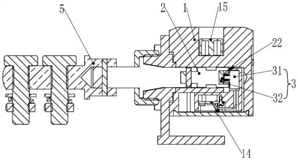
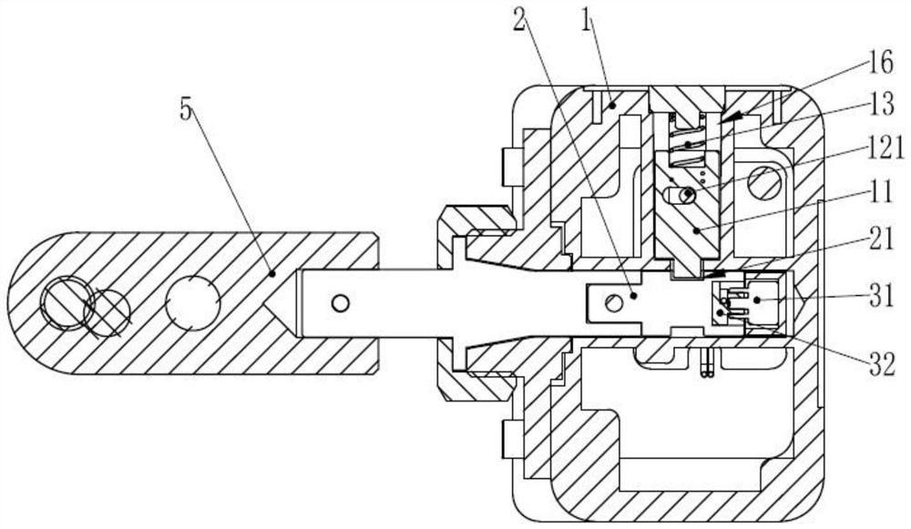
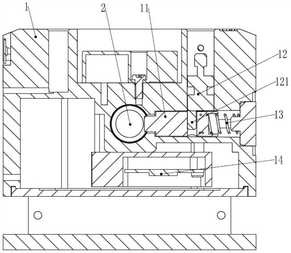
The invention discloses a lock with a state detection function and a state detection method using the lock, and belongs to the technical field of power transmission and transformation. The lock comprises a lock body and a lock rod and further comprises a trigger resistor assembly, the trigger resistor assembly comprises a first trigger piece and a second trigger piece, and the first trigger piece or the second trigger piece is provided with a trigger resistor; and the lock body is provided with a detection module and a lock rod channel, the first trigger piece is arranged in the lock rod channel, and the second trigger piece is arranged at one end of the lock rod. When the lock rod is inserted into the lock rod channel and is inserted into the locking position, the first trigger piece makes contact with the second trigger piece, and the detection module is used for detecting the resistance value of the trigger resistor or the resistance value change value of the trigger resistor. The state detection method comprises a locking step and an unlocking step. According to the lock and the state detection method, the problem that misoperation accidents are caused due to the fact that the state feedback of whether a lock is locked or unlocked is difficult to obtain by the existing lock and an existing state detection method is solved.

Description

technical field [0001] The invention relates to the technical field of power transmission and transformation, in particular to a lock with state detection and a state detection method using the same. Background technique [0002] In the field of power transmission and transformation, many locks require real feedback status. Such as ground wire lock: In order to maintain the safety of power grid operation, lines and electrical equipment need to be tested before they are put into use or undergo regular inspection and maintenance. In the inspection and maintenance of electrical equipment, in order to ensure the safety of the operators, a temporary grounding wire must be connected before the inspection and inspection, and at the same time, it can also ensure the operation safety of the entire power grid during the power transmission process after the inspection. In addition, after the maintenance is completed, the ground wire needs to be removed to supply power to the electrica...

Claims


Application Information

Patent Timeline
Patent Type & Authority Applications(China)
IPC IPC(8): E05B17/22E05B35/00E05B41/00
CPCE05B17/22E05B35/00E05B35/001E05B41/00
Inventor 刘晋武黄梦马琳王金兴
Owner CYG CONTRON
Learn More