
Fault detection device and method for electrified railway AT stations

A technology for electrified railways and fault detection. It is applied in the direction of fault location, fault detection according to conductor type, etc. It can solve problems such as failure to timely and accurately find faults, isolate faults, and burn out, so as to reduce the scope of power outages, improve reliability, and avoid magnifying effect

Active Publication Date: 2018-12-18
SOUTHWEST JIAOTONG UNIV
View PDF13 Cites 5 Cited by
  • Summary
  • Abstract
  • Description
  • Claims
  • Application Information

AI Technical Summary

Problems solved by technology

[0005] The purpose of the present invention is to provide a fault detection device and method for the AT station of an electrified railway, which can effectively solve the technical problems in the prior art that the fault cannot be found and isolated in time and accurately, and can completely eliminate the train from When the non-fault section enters the fault section, the pantograph short-connects the catenary to cause a new short circuit, and the train enters the non-electric zone with load, causing arcing and burning, and even burns the catenary to cause accidents and hidden dangers, thereby improving Reliability of power supply system and efficiency of rail transport

Method used


Image

  • Fault detection device and method for electrified railway AT stations
  • Fault detection device and method for electrified railway AT stations
  • Fault detection device and method for electrified railway AT stations

Examples


Embodiment 1

[0031] Such as figure 1 with figure 2 As shown, the embodiment of the present invention provides a fault detection device for an AT station of an electrified railway, which selects the left-adjacent AT station AS1, the middle AT station AS2, and the right-adjacent AT station AS3 in the AT power supply system of the gasification railway. The input terminal of the fault detection device of AS2 is respectively connected to the test terminals of the left neighbor AT station AS1, the middle AT station AS2, and the right neighbor AT station AS3, and its output terminal is connected to the left neighbor AT station AS1, the middle AT station AS2, and the right neighbor AT station AS3 The control terminal and the electric regulation information sending terminal DD, wherein, the left neighbor AT station AS1, the middle AT station AS2, and the right neighbor AT station AS3 respectively set two sectionalizers on the catenary T of the respective exits and the sectionalizers They are conn...

Embodiment 2

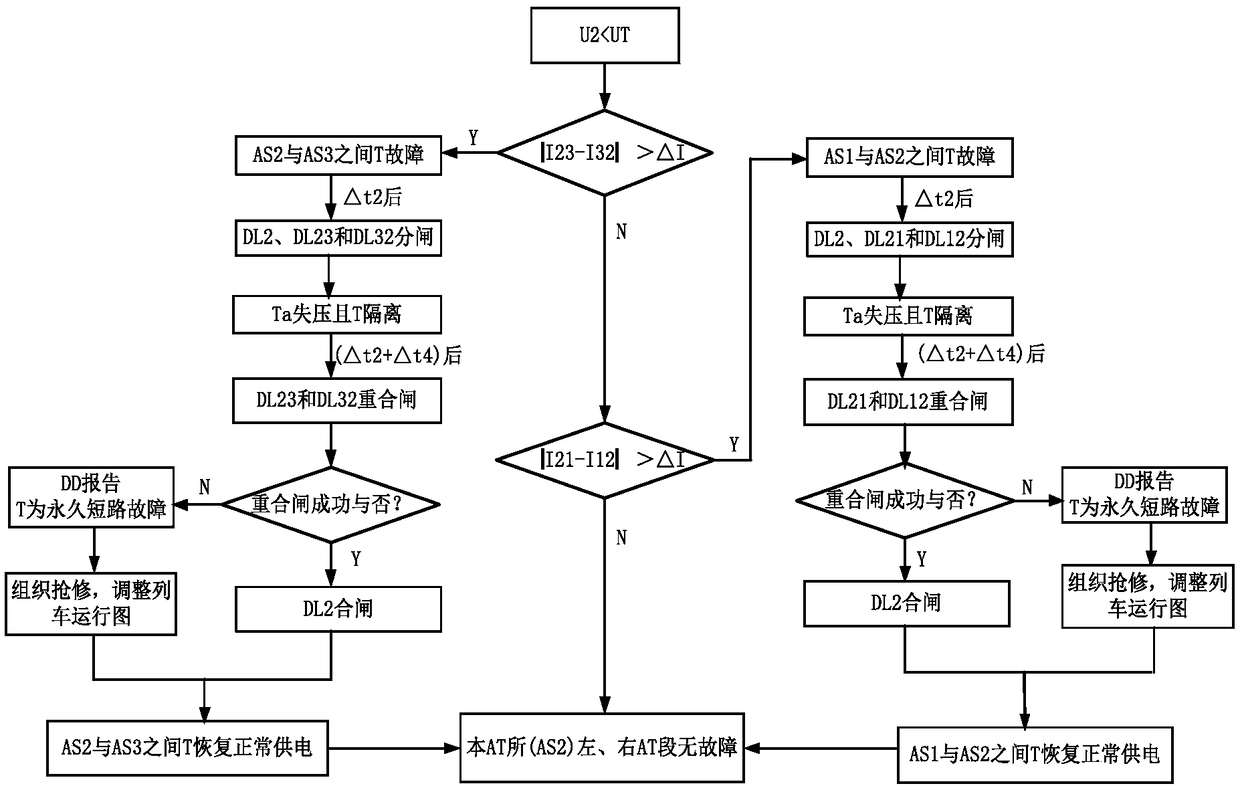
[0039] Such as image 3 As shown, the embodiment of the present invention provides a fault detection method for electrified railway AT stations using the fault detection device described in the first embodiment above. The fault detection device is installed in the middle AT station AS2, and the train converter network is set The side closing reaction time is △t1, the opening time of the catenary T circuit breaker is △t2, the time interval for the train converter to resume normal operation after detecting that the catenary voltage is normal is △t3, and the reclosing time after the catenary T is short-circuited The specific steps of the fault detection method are as follows: determine whether the voltage value U2 measured by the voltage transformer YH2 is lower than the state threshold UT;

[0040] If yes, the train loses pressure and is in the range of pressure loss. After △t1 second, the grid side of the train converter is closed. At this time, the load = 0, and at the same ti...


PUM


Abstract

The invention discloses a fault detection device and method for electrified railway AT stations, and relates to the technical field of traction power supply for electrified railways. According to thefault detection device, the input end of the fault detection device mounted in the middle AT station of the three AT stations in an electrified railway AT power supply system is connected with the test ends of the left adjacent AT station, the middle AT station and the right adjacent AT station; the output end of the fault detection device mounted in the middle AT station of the three AT stationsin the electrified railway AT power supply system is connected with the control ends and the electric tuning information sending ends of the left adjacent AT station, the middle AT station and the right adjacent AT station; two sectionalizers are arranged on a contact net of an outlet of each of the left adjacent AT station, the middle AT station and the right adjacent AT station; and the sectionalizers are connected through transition regions. The fault detection device and method can effectively solve the technical problems existing in the prior art that a fault cannot be timely and accurately found and isolated, a new short circuit is caused because a pantograph is short-circuited with the contact net when a train is driven into a fault section from a non-fault section, arc discharge and burning loss are caused and even the contact net is burnt out to cause an accident because the train with a load enters a no-power region, and the like.

Description

technical field [0001] The invention belongs to the technical field of traction power supply measurement and control for AC electrified railways. Background technique [0002] Compared with the direct power supply method, the AT power supply method of the electrified railway has stronger power supply capacity and longer power supply arm length, which can reduce electric phase separation and dead zones. Therefore, almost all high-speed railways in my country choose the AT power supply method. [0003] The current high-speed rail power supply method adopts the uplink and downlink full parallel connection, which has the advantage that the power supply capacity can be further enhanced, but the disadvantage is that once a failure occurs, the scope of influence will be further expanded. An improvement scheme is to segment the traction substation, AT substation, and partition substation, that is, to install a segmenter on the catenary at the outlet of the AT substation, so as to re...

Claims


Application Information

Patent Timeline
Patent Type & Authority Applications(China)
IPC IPC(8): G01R31/08
CPCG01R31/086Y04S10/52
Inventor 李群湛易东陈民武
Owner SOUTHWEST JIAOTONG UNIV
Learn More