
Power tube test circuit and power supply protection chip

A technology for testing circuits and power tubes, applied in the field of circuits, can solve problems such as difficult large current detection, unstable test results, heating of power tubes, etc., and achieve the effect of meeting test requirements

Pending Publication Date: 2021-11-16
SHANGHAI AWINIC TECH CO LTD
View PDF0 Cites 0 Cited by
  • Summary
  • Abstract
  • Description
  • Claims
  • Application Information

AI Technical Summary

Problems solved by technology

Large current tends to generate a large voltage drop across the power tube, and the power tube will generate heat
If tested directly, it will lead to unstable test results
Moreover, the probes for mass production testing are not allowed to input large currents.
[0004] At present, the mass production test of power protection chips is still equipped with low current gears to detect small currents. It is difficult to detect large currents and meet test requirements.

Method used


Image

  • Power tube test circuit and power supply protection chip
  • Power tube test circuit and power supply protection chip

Examples


Embodiment Construction

[0026] The solutions in the embodiments provided in the present application will be described below with reference to the drawings in the present application.

[0027] The terms "first" and "second" in the embodiments of the present application are used for description purposes only, and cannot be understood as indicating or implying relative importance or implicitly indicating the quantity of indicated technical features. Thus, a feature defined as "first" and "second" may explicitly or implicitly include one or more of these features.

[0028] First, some technical terms involved in the embodiments of the present application are introduced.

[0029] In the current test of the power tube, how to test the high current has always been a difficult point in the industry. On the one hand, the high current is likely to cause a large voltage drop across the power tube, which will cause the power tube to heat up, cause overheating protection, and cannot be stabilized. test. On the ...


PUM


Abstract

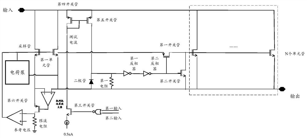
The invention provides a power tube test circuit, the circuit which comprises a power tube, a control circuit and a sampling tube, the power tube comprises N + 1 unit tubes, the N + 1 unit tubes comprise a first unit tube and N unit tubes, in a test mode, the control circuit closes the N unit tubes and only opens the first unit tube, so that the output current of the power tube is reduced, therefore, the large current is converted into the small current which can be tested through the probe, and the stability of the test is improved.

Description

technical field [0001] The present application relates to the field of circuit technology, in particular to a power tube test circuit and a power supply protection chip. Background technique [0002] In the power protection chip, many will integrate the power tube. Among them, the power tube is a transistor that serves as the final output in the amplifier circuit. The power tube can be based on the collector maximum dissipation power P CM The size is divided into high-power tubes and small-power tubes. Wherein, the power tube whose collector maximum dissipation power is greater than 1 watt (W) can be a high-power tube, and the power tube whose collector maximum dissipation power is less than 1W can be a low-power tube. [0003] These power tubes will flow ampere-level high current during normal operation. Large current tends to generate a large voltage drop across the power tube, and the power tube will generate heat. If it is tested directly, it will lead to unstable t...

Claims


Application Information

Patent Timeline
Patent Type & Authority Applications(China)
IPC IPC(8): G01R31/26
CPCG01R31/2639
Inventor 姜艳
Owner SHANGHAI AWINIC TECH CO LTD
Learn More