
Energy-saving and environment-friendly wire bending machine

An energy-saving, environmentally friendly, wire bending machine technology, applied in metal wire drawing, manufacturing tools, metal processing equipment, etc.

Pending Publication Date: 2021-11-19
苏州斯特丹自动化设备有限公司
View PDF0 Cites 0 Cited by
  • Summary
  • Abstract
  • Description
  • Claims
  • Application Information

AI Technical Summary

Problems solved by technology

[0004] The purpose of the present invention is to provide an energy-saving and environment-friendly wire bending machine to solve the problem that the wire rod and the rotating shaft may not be tightly bonded in the existing wire bending machine proposed in the above-mentioned background technology

Method used

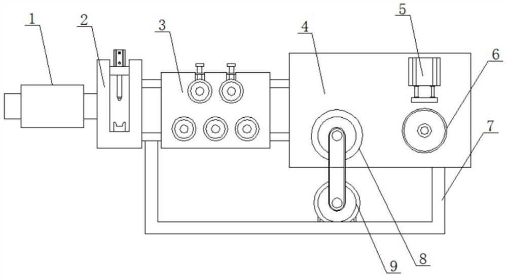
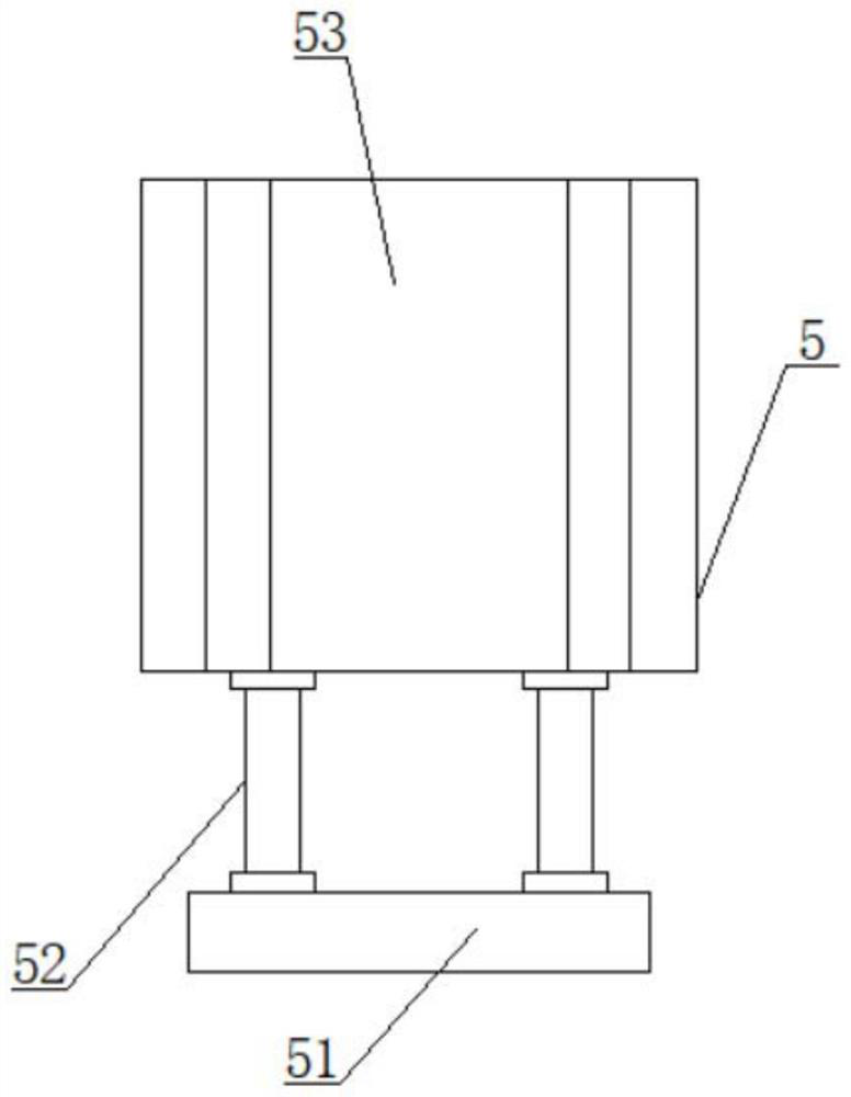
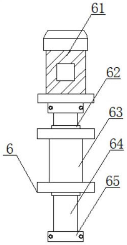

Image

  • Energy-saving and environment-friendly wire bending machine
  • Energy-saving and environment-friendly wire bending machine
  • Energy-saving and environment-friendly wire bending machine

Examples


Embodiment Construction

[0018] The following will clearly and completely describe the technical solutions in the embodiments of the present invention with reference to the accompanying drawings in the embodiments of the present invention. Obviously, the described embodiments are only some, not all, embodiments of the present invention. Based on the embodiments of the present invention, all other embodiments obtained by persons of ordinary skill in the art without making creative efforts belong to the protection scope of the present invention.

[0019] In the description of the present invention, it should be noted that the terms "upper", "lower", "inner", "outer", "front end", "rear end", "both ends", "one end", "another end" The orientation or positional relationship indicated by etc. is based on the orientation or positional relationship shown in the drawings, and is only for the convenience of describing the present invention and simplifying the description, rather than indicating or implying that ...


PUM


Abstract

The invention discloses an energy-saving and environment-friendly wire bending machine which comprises a wire inlet pipe and a shearing mechanism. The shearing mechanism is arranged at the right end of the wire inlet pipe, the wire inlet pipe is fixedly connected with the shearing mechanism through bolts, a straightening mechanism is arranged at the right end of the shearing mechanism, a side plate is arranged at the right end of the straightening mechanism, and a wire feeding shaft is arranged at the lower end of the surface side of the side plate. In the energy-saving and environment-friendly wire bending machine, an attaching mechanism is arranged at the upper end of a winding mechanism and is fixedly connected with the side plate through bolts, when a wire is wound, the attaching mechanism drives a pressing plate and the wire to extrude each other through transmission shafts, the problem that attaching is not tight in early summer during winding cannot happen, a rotating shaft and a sleeve pipe are fixed, and therefore during winding, a lead screw is driven to move through forward and reverse rotation of a second motor so that the rotating shaft can move left and right back and forth at the surface end of the lead screw, the wire can be uniformly and fully paved at the surface end of the rotating shaft when wound, and the problem that the rotating shaft and the wire are not uniform cannot occur.

Description

technical field [0001] The invention belongs to the technical field related to wire rod processing, and in particular relates to an energy-saving and environment-friendly wire bending machine. Background technique [0002] Generally speaking, a wire bending machine is a device that automatically bends wires to form various mechanical and instrument components including springs, frames, and operating pins. Form 2D or even 3D components. [0003] The existing wire bending machines have the following problems: when the existing wire bending machines are working, most of them use the rotation of the rotating shaft to achieve the effect of bending the wire, but because the wire to be bent itself has a certain degree of firmness, it is only necessary to pass the The rotation of the shaft may cause insufficient tension of the wire and the loose fit between the wire and the shaft, resulting in incomplete bending. Contents of the invention [0004] The purpose of the present inve...

Claims


Application Information

Patent Timeline
Patent Type & Authority Applications(China)
IPC IPC(8): B21C47/02B21C47/34B21C19/00B21F11/00
CPCB21C47/02B21C47/34B21C19/00B21F11/00
Inventor 唐可万栋梁
Owner 苏州斯特丹自动化设备有限公司
Learn More