Shell cutting device for electric connector production and machining

A technology of electrical connectors and cutting devices, which is applied in the field of shell cutting devices for the production and processing of electrical connectors, can solve the problems of inconvenient continuous cutting, inconvenient shell, and low cutting efficiency, and achieve convenient continuous cutting, high cutting efficiency, The effect of ensuring cutting accuracy

Inactive Publication Date: 2021-11-19
HUNAN HUAFENG XINYU ELECTRONICS CO LTD
View PDF0 Cites 0 Cited by
  • Summary
  • Abstract
  • Description
  • Claims
  • Application Information

AI Technical Summary

Problems solved by technology

[0003] Most of the existing cutting devices can only cut individually, which is inconvenient for continuous cutting, and the cutting efficiency is low. At the same time, it is inconvenient to unload the cut shell

Method used


Image

  • Shell cutting device for electric connector production and machining
  • Shell cutting device for electric connector production and machining
  • Shell cutting device for electric connector production and machining

Examples


Embodiment 1

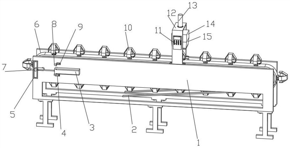
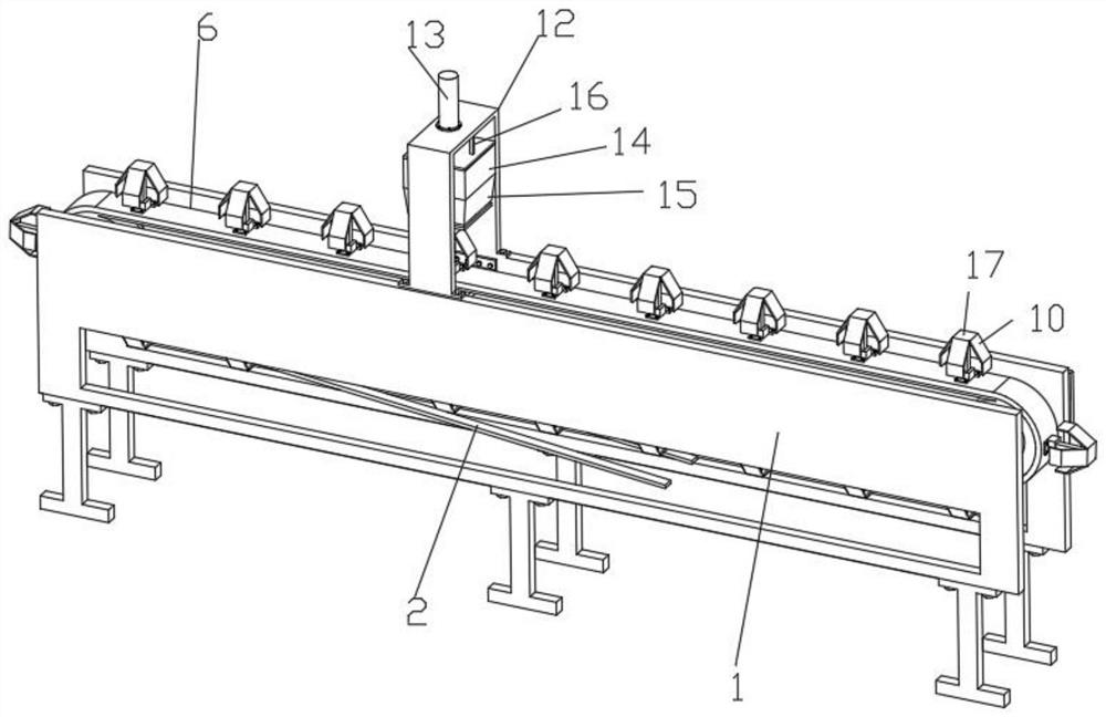
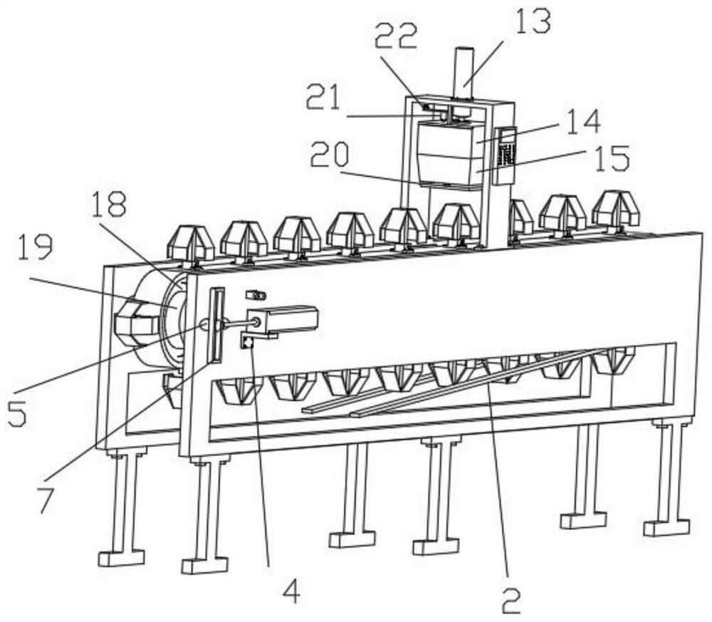
[0030] like figure 1 , 2 , 3, 4, 5, and 6, a shell cutting device for the production and processing of electrical connectors, including a support frame 1, the support frame 1 is connected with an intermittent movement structure for the intermittent movement of the shell, and the intermittent movement structure includes a first cylinder 3 , the first support seat 4, the square frame 5, the square frame 5, the conveyor belt 6, the Z-shaped shaft 7, the ring gear 18, the rotating roller 19 and the timing belt 23, the first support seat 4 is fixedly installed on the outer wall of the support frame 1, The top of the first support base 4 is fixedly connected with the first cylinder 3, the output end of the first cylinder 3 is fixedly connected with the square frame 5, and the inner wall of the support frame 1 is evenly and fixedly connected with the rotating roller 19 through the fixedly connected bearing, and the rotating roller 19 The outer wall is fixedly connected with a ring g...

Embodiment 2

[0036] Embodiment 2 is a further improvement to Embodiment 1.

[0037] like figure 1 , 3 As shown, the support frame 1 is also connected with an automatic control structure, the automatic control structure includes a first contact switch 8, a first mounting base 9, a second contact switch 21 and a second mounting base 22, the left side wall of the first mounting base 9 The first contact switch 8 is fixedly connected, and the first mount 9 is fixedly mounted on the side wall of the support frame 1, the second mount 22 is fixedly mounted on the top of the n-shaped plate 12, and the bottom of the second mount 22 is fixedly connected with The second contact switch 21, after the square frame 5 contacts the first contact switch 8, the controller 11 controls the first cylinder 3 to stop and the second cylinder 13 to start, and after the square cylinder 14 contacts the second contact switch 21, the controller 11 controls the first cylinder 3 to stop. Cylinder 3 starts and second cyl...


PUM


Abstract

The invention discloses a shell cutting device for electric connector production and machining, and relates to the technical field of electric connector machining. The shell cutting device comprises a supporting frame, wherein the supporting frame is connected with an intermittent movement structure for intermittent movement of a shell, insertion structures for insertion of the shell are uniformly and fixedly connected to the outer wall of the intermittent movement structure, an n-shaped plate is fixedly connected to the top of the supporting frame, a controller is fixedly connected to the outer wall of the n-shaped plate, a second air cylinder is fixedly connected to the top of the n-shaped plate, a square barrel is fixedly connected to the output end of the second air cylinder, a conical cutter for cutting is fixedly connected to the bottom of the square barrel, the n-shaped plate is connected with a pressing structure for pressing the shell, and the inner wall of the right end of the supporting frame is connected with an automatic discharging structure for automatic discharging. The shell cutting device facilitates continuous cutting and has high cutting efficiency.

Description

technical field [0001] The invention relates to the technical field of electrical connector processing, in particular to a shell cutting device for the production and processing of electrical connectors. Background technique [0002] In addition to meeting the general performance requirements, the electrical connector must meet the requirements of good contact, reliable operation, and convenient maintenance. Whether the electrical connector is reliable or not directly affects the normal operation of the aircraft circuit and involves the safety of the entire host. For this reason, the host circuit has very strict requirements on the quality and reliability of the electrical connector, and because of the high quality and reliability of the electrical connector, it is also widely used in military systems such as aviation, aerospace, and national defense. Commonly used classification methods for electrical connectors include shape, structure, use, etc. When the connector is used...

Claims


Application Information

Patent Timeline
Patent Type & Authority Applications(China)
IPC IPC(8): B26D1/06B26D5/00B26D7/01B26D7/06B26D7/18
Inventor 谢开满
Owner HUNAN HUAFENG XINYU ELECTRONICS CO LTD
Why Eureka
Try Eureka