Winding head arrangement for electric rotating machine

A technology for a rotating electrical machine and a winding head, which is used in the manufacture of a winding head device for a rotating electrical machine and the field of rotating electrical machines, can solve the problems of increasing the overall length and weight of the rotating electrical machine.

Pending Publication Date: 2021-11-19
SIEMENS AG
View PDF10 Cites 0 Cited by
  • Summary
  • Abstract
  • Description
  • Claims
  • Application Information

AI Technical Summary

Problems solved by technology

In addition, the overall length and weight of the rotating electrical machine increases

Method used


Image

  • Winding head arrangement for electric rotating machine
  • Winding head arrangement for electric rotating machine
  • Winding head arrangement for electric rotating machine

Examples


Embodiment Construction

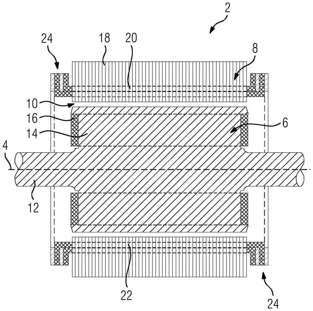
[0043] figure 1 A longitudinal section through a rotary electric machine 2 is shown, which is embodied as a synchronous machine by way of example. The synchronous machine has a rotor 6 rotatable about an axis of rotation 4 , embodied as an example as a salient-pole armature, and a stator 8 adjacent to the rotor 6 . Between the rotor 6 and the stator 8 there is a gap 10 which is embodied in particular as an air gap. The rotor shaft 4 defines an axial direction, a radial direction and a circumferential direction. The rotor 6 includes a shaft 12 and a salient pole 14 with an excitation winding 16 . Alternatively, the rotor 6 has permanent magnets or a squirrel-cage winding.

[0044] The stator 8 comprises a magnetically conductive, in particular eddy current-suppressing, stator element 18 , for example embodied as laminations, and a stator winding 20 . The stator winding 20 comprises a coil bar 22 , for example made of copper, which extends in the axial direction through the ...


PUM


Abstract

The invention relates to a winding head arrangement (4) for an electric rotating machine. According to the invention, to provide a winding head arrangement (24) which is simpler and more cost-effective to produce compared with the prior art, the winding head arrangement (24) has at least one main body (26, 28) and a plurality of conductors (30) made of a first metal material, wherein the main body (26, 28) comprises an electrically conductive material having an electrically insulating coating (35), the conductors (30) are connected to the main body (26, 28) via the electrically insulating coating (35) and the conductors (30) are applied to the electrically insulating coating (35) by means of a first additive manufacturing method.

Description

technical field [0001] The invention relates to a winding head arrangement for a rotating electrical machine. [0002] Furthermore, the invention relates to a stator for a rotating electrical machine having a magnetic field-conducting stator element and at least one such winding head arrangement. [0003] Furthermore, the invention relates to a rotating electric machine having at least one such stator. [0004] Furthermore, the invention relates to a method of manufacturing a winding head arrangement for a rotating electrical machine. Background technique [0005] The stator windings of rotating electric machines capable of operating at least one megawatt are usually implemented as formed coils. Formed coils are produced, for example, by means of drawing, casting or powder metallurgy. At the ends of the profiled coil there is a winding end, which forms the conductor of the profiled coil by bending and bending. This winding head requires significant axial space. Ohmic lo...

Claims


Application Information

Patent Timeline
Patent Type & Authority Applications(China)
IPC IPC(8): H02K3/50H02K15/00
CPCH02K3/50H02K15/0081H02K2203/09H02K3/38H02K15/105
Inventor 卡斯滕·布拉赫延斯·达尔·詹森哈特穆特·劳赫奥拉夫·雷梅雅各布·施内克奥利弗·施蒂尔
Owner SIEMENS AG
Why Eureka
Try Eureka