
Range hood and control method thereof

A technology for range hoods and smoke deflectors, which is applied in the fields of oil fume removal, heating methods, household heating, etc., and can solve the problems of grease loss, large difference in smoke generation, and impact on appearance, so as to reduce material requirements and use The effect of long life and effect enhancement

Pending Publication Date: 2021-11-23
NINGBO FOTILE KITCHEN WARE CO LTD
View PDF11 Cites 1 Cited by
  • Summary
  • Abstract
  • Description
  • Claims
  • Application Information

AI Technical Summary

Problems solved by technology

[0006] 1. When the traditional smoke deflector range hood is used on an ordinary double stove, the stir-fry side and the soup side have a large difference in the amount of cooking smoke, so it is impossible to adjust the air volume or the area of ​​​​the air inlet to adapt to the cooking situation;
[0007] 2. There are some range hoods with lifting smoke deflectors, although the overall air inlet can be adjusted up and down according to the size of the oil fume, but it mainly adopts a lifting structure similar to an electric push rod + guide rail. If it is exposed to the oil circuit environment, because the guide rail and push rod The accumulation of oil will lead to the loss of grease, or the accumulation of dirt will cause jamming, which will easily lead to failure; and some products with electric push rods or guide rails external to the outside of the fan frame, the external mechanism will cause the product volume to increase, which will affect The shape is beautiful or it cannot be wrapped in the cabinet

Method used


Image

  • Range hood and control method thereof
  • Range hood and control method thereof
  • Range hood and control method thereof

Examples


Embodiment Construction

[0090] Embodiments of the present invention are described in detail below, examples of which are shown in the drawings, wherein the same or similar reference numerals denote the same or similar elements or elements having the same or similar functions.

[0091] In describing the present invention, it should be understood that the terms "center", "longitudinal", "transverse", "length", "width", "thickness", "upper", "lower", "front", " Back", "Left", "Right", "Vertical", "Horizontal", "Top", "Bottom", "Inner", "Outer", "Clockwise", "Counterclockwise", "Axial", The orientation or positional relationship indicated by "radial", "circumferential", etc. is based on the orientation or positional relationship shown in the drawings, and is only for the convenience of describing the present invention and simplifying the description, rather than indicating or implying the referred device or element must have a particular orientation, be constructed, and operate in a particular orientatio...


PUM


Abstract

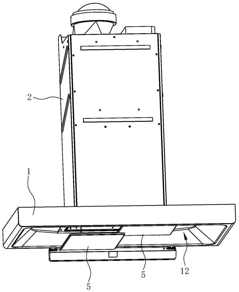
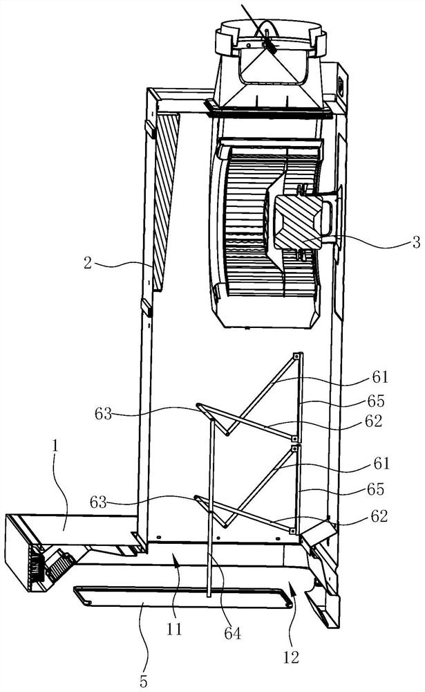
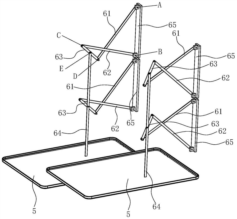
The invention discloses a range hood. The range hood comprises an exhaust fume collecting hood, a fan frame which is arranged above the exhaust fume collecting hood and a fan system which is arranged in the fan frame, an air inlet is formed in the exhaust fume collecting hood, a smoke guiding plate is arranged below the air inlet, the range hood further comprises a movement mechanism used for driving the smoke guiding plate to ascend and descend, the range hood is characterized in that the movement mechanism comprises a lifting mechanism and a transmission rod driven by the lifting mechanism to ascend and descend, the lifting mechanism comprises a cross connecting rod mechanism extending transversely and an output connecting rod connected to the output end of the cross connecting rod mechanism, the output connecting rod is connected with the transmission rod, and the transmission rod is fixedly connected with the smoke guiding plate and can drive the smoke guiding plate to ascend and descend. Compared with the prior art, the range hood has the advantages that the multi-connecting-rod mechanism is arranged, and a linear motion track is formed after rotating connection, so that guide rail guiding is not needed, through a structure of a pure rotating connection pair, the range hood is free of harsh environment influences such as lampblack.

Description

technical field [0001] The invention relates to a cooking fume purification device, in particular to a range hood and a control method for the range hood. Background technique [0002] Range hoods have become one of the indispensable kitchen appliances in modern families. The range hood uses the principle of fluid dynamics to work, sucks and exhausts the range hood through a centrifugal fan installed inside the range hood, and uses a filter to filter some grease particles. The centrifugal fan includes a volute, an impeller installed in the volute and a motor that drives the impeller to rotate. When the impeller rotates, a negative pressure suction is generated in the center of the fan, and the oil fume under the range hood is sucked into the fan, and after being accelerated by the fan, it is collected by the volute and guided out of the room. [0003] Generally, range hoods include top-suction and side-suction types. Top-suction range hoods use the principle of fume rising...

Claims


Application Information

Patent Timeline
Patent Type & Authority Applications(China)
IPC IPC(8): F24C15/20
CPCF24C15/2021
Inventor 何立博
Owner NINGBO FOTILE KITCHEN WARE CO LTD
Learn More