Centering device

A technology of centering device and centering block, applied in the direction of spraying device, etc., can solve the problems of affecting product quality, the deviation of the center line of the non-stick pan and the center line of the suction cup, the deviation of the position of the non-stick pan and the theoretical position, etc.

Pending Publication Date: 2021-11-26
黄山诺帆科技装备制造有限公司
View PDF0 Cites 0 Cited by
  • Summary
  • Abstract
  • Description
  • Claims
  • Application Information

AI Technical Summary

Problems solved by technology

In order to improve production efficiency, the non-stick pan is mostly placed on the conveying mechanism in the prior art, and the non-stick pan is transported to the primer spraying device, the intermediate paint spraying device and the top paint spraying device through the conveying mechanism for spraying operations, but not During the process of the sticky pan being conveyed forward on the conveying mechanism, the non-stick pan will inevitably vibrate and deviate from the original conveying center line of the non-stick pan, and the deviation direction and deviation distance are uncertain
[0003] In order to solve the above problems, most of the industries in the industry set eight-shaped guide plates on the racks on both sides of the conveying mechanism. The opening of the guide plates gradually decreases from upstream to downstream. The guide and limit of the inner surface of the plate make the centerline of the non-stick pan from the downstream outlet consistent with the centerline of the suction cup, but for the guide plate, in order to ensure that the non-stick pan can pass through the outlet smoothly, the outlet The size of the non-stick pan should be slightly larger than the outer diameter of the non-stick pan, or the guide plate must have a certain amount of floating, which will inevitably cause a certain amount of deviation between the actual position of the non-stick pan and the theoretical position, resulting in the center line of the non-stick pan and the suction cup. There is a deviation in the center line, and the final result is that the paint on the non-stick pan is uneven, which affects the quality of the product

Method used


Image

  • Centering device
  • Centering device

Examples


Embodiment Construction

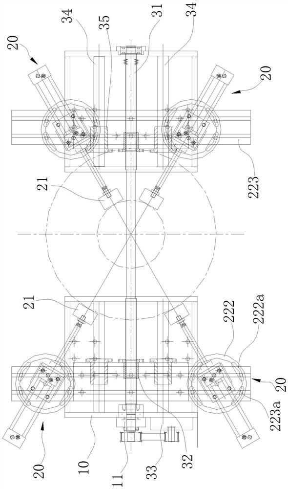
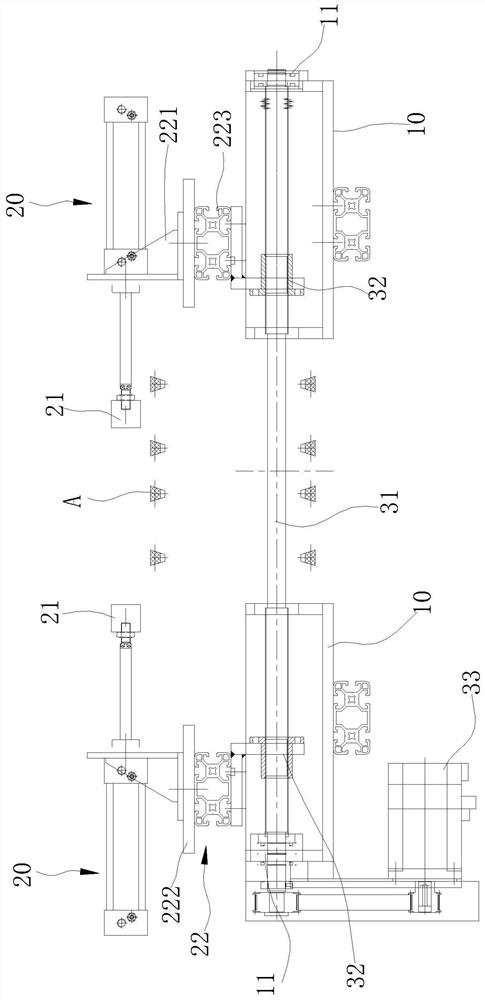
[0009] Such as figure 1 , figure 2 As shown, a centering device, at least three centering blocks 21 are arranged on the frame 10 on both sides of the conveying unit A, the centering blocks 21 are connected with the driving mechanism and move in the same horizontal plane, and multiple centering blocks 21 move When being on the same circle with different radii determined by the center of the circle (the meaning is that the center of the circle is determined, there can be multiple circles with different radii, and the three centering blocks 21 can be on the same circle with different radii when they move. The inner surface of the centering block 21 facing the center of the circle is a plane (each inner surface is tangent to the same circle), and the bottom of the centering block 21 is higher than the conveying unit A. The drive mechanism here can be a linear drive mechanism or a swing drive mechanism or other forms, as long as the drive to the centering block 21 can be realized...


PUM


Abstract

The invention aims at providing a centering device. It can be guaranteed that the center line of a non-stick pan is consistent with the center line of a suction cup, and the precision is high. At least three centering blocks are arranged on the portions, on the two sides of a conveying unit, of a rack, and the centering blocks are connected with a driving mechanism and move in the same horizontal plane; and the multiple centering blocks are located on the same circumference with different radiuses and circle centers determined when moving, and the bottommost portions of the centering blocks are higher than the conveying unit. According to the scheme, the driving mechanism drives the centering blocks to be close to or away from each other synchronously, and no matter how the centering blocks move, the centering blocks are located on the same circumference with the circle centers determined, so that when the centering blocks clamp the outer wall of the non-stick pan, the non-stick pan can be positioned to the position where the center of the non-stick pan coincides with the circle centers of the multiple centering blocks, accurate centering of the non-stick pan is achieved, the subsequent spraying effect is guaranteed, and the product quality is improved.

Description

technical field [0001] The invention relates to the technical field of spraying equipment, in particular to a centering device. Background technique [0002] Non-stick pans are popular among consumers for their non-stick performance. In order to ensure non-stick performance, the pan embryo needs to be sprayed with three layers of primer, middle paint and top coat during the production process. For the spraying of non-stick pans, the most important thing is the uniformity of the spraying, because the positions of the primer spraying device, the intermediate paint spraying device and the top paint spraying device are fixed, that is, the position of the centerline of the nozzle is fixed. It does not move, so it is necessary to ensure that the suction cup under the nozzle is adsorbed to the center of the bottom of the non-stick pan as much as possible. In addition, the suction cup and the center line of the nozzle itself coincide, so that the center of the incoming material (non...

Claims


Application Information

Patent Timeline
Patent Type & Authority Applications(China)
IPC IPC(8): B05B13/02
CPCB05B13/0271B05B13/0221
Inventor 陈从培
Owner 黄山诺帆科技装备制造有限公司
Why Eureka
Try Eureka