
Centering structure and turbine test device with centering structure

A technology for power turbines and mounting holes, which is applied in the field of aero-engines, can solve the problem that the installation side of the casing and the installation side of the volute cannot be centered, and achieve the effect of achieving precise centering and ensuring accurate positioning

Active Publication Date: 2020-07-31
AECC HUNAN AVIATION POWERPLANT RES INST
View PDF6 Cites 0 Cited by
  • Summary
  • Abstract
  • Description
  • Claims
  • Application Information

AI Technical Summary

Problems solved by technology

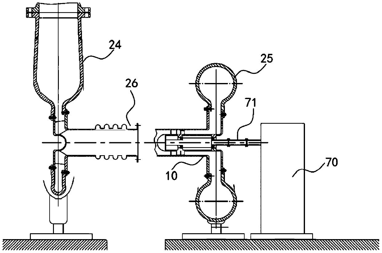
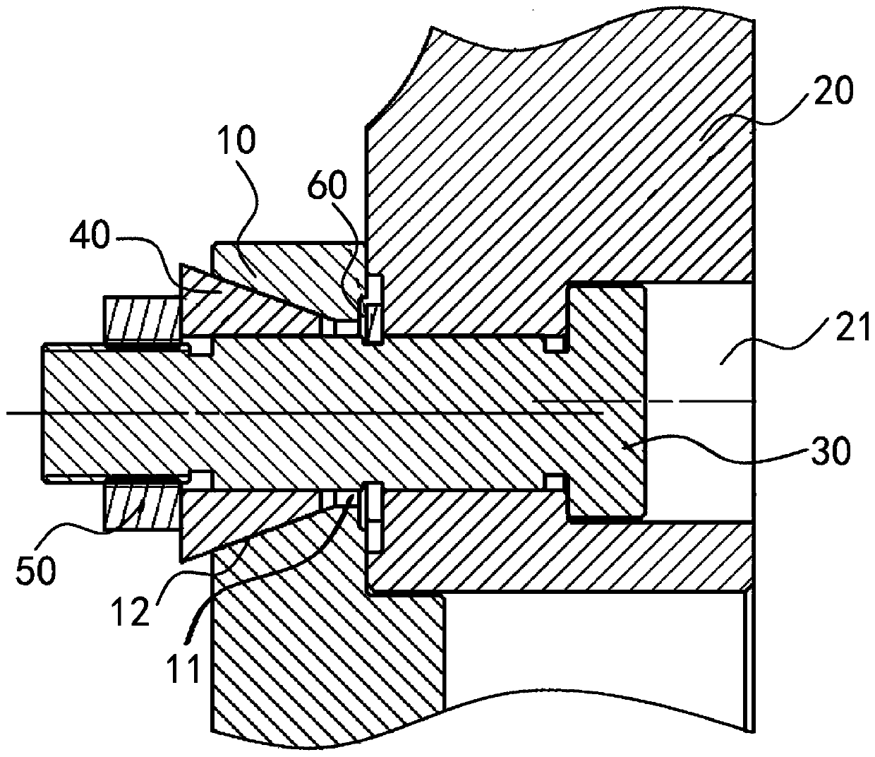
[0004] The present disclosure provides a centering structure and a turbine test device with it, so as to solve the problem in the prior art that the casing mounting edge and the volute mounting edge of the test piece cannot be centered

Method used


Image

  • Centering structure and turbine test device with centering structure
  • Centering structure and turbine test device with centering structure
  • Centering structure and turbine test device with centering structure

Examples


Embodiment Construction

[0036] Typical embodiments that embody the features and advantages of the present disclosure will be described in detail in the following description. It should be understood that the present disclosure can have various changes in different embodiments without departing from the scope of the present disclosure, and that the description and drawings therein are illustrative in nature and not intended to limit the present disclosure. public.

[0037] In the following description of various exemplary embodiments of the present disclosure, reference is made to the accompanying drawings, which form a part hereof, and in which are shown by way of example various exemplary structures, systems and procedures that may implement aspects of the present disclosure . It is to be understood that other specific arrangements of components, structures, exemplary devices, systems and steps may be utilized and structural and functional modifications may be made without departing from the scope ...


PUM


Abstract

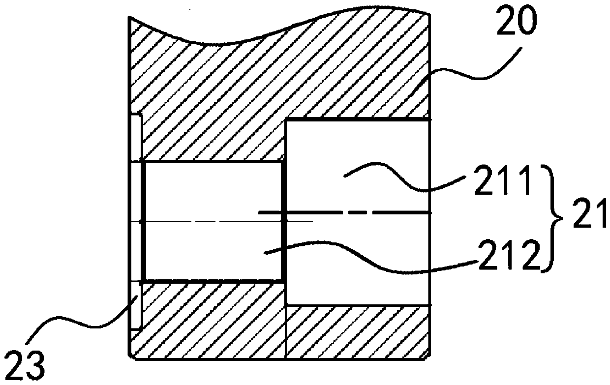
The invention relates to the technical field of aero-engines, and provides a centering structure and a turbine test device with the centering structure. The centering structure is used for connectinga power turbine test piece and a volute. A first mounting hole is formed in the power turbine test piece, a second mounting hole is formed in the volute, the centering structure comprises a fastener,a sliding block and a locking piece, the fastener penetrates through the second mounting hole and the first mounting hole, and a reserved gap is formed between the fastener and the first mounting hole; the sliding block is arranged in the reserved gap; and the locking piece is detachably connected with the fastener and abuts against one end, far away from the second mounting hole, of the sliding block so that the power turbine test piece is fixedly connected with the volute. The power turbine test piece and the volute can be connected through the fastener, the sliding block and the locking piece, accurate centering of the power turbine test piece and the volute can be achieved, and thus the problem in the prior art that test piece casing installation edge and the volute installation edge cannot be centered is solved.

Description

technical field [0001] The present disclosure relates to the technical field of aero-engines, in particular to a centering structure and a turbine test device having the centering structure. Background technique [0002] At present, before the turbine test, the concentricity between the test piece and the dynamometer needs to be adjusted to ensure the normal operation of the test piece. However, the existing technology is manually adjusted by the operator, but because the change of the position of the dynamometer is realized through the plug adjustment gasket, the whole adjustment is difficult and time-consuming, so it is necessary to reduce the test piece and dynamometer as much as possible Adjustment of concentricity between. [0003] However, in the prior art, in order to facilitate the installation of the test piece, the mounting edge of the casing of the test piece and the mounting edge of the volute are directly connected by bolts, and a large gap is designed between ...

Claims


Application Information

Patent Timeline
Patent Type & Authority Applications(China)
IPC IPC(8): G01M13/00G01M15/02G01M15/14F16B39/24F16B43/00
CPCG01M13/00G01M15/02G01M15/14F16B39/24F16B43/00
Inventor 宋石平刘顺金方华郭志中吴支繁
Owner AECC HUNAN AVIATION POWERPLANT RES INST
Learn More